I think you can do better. I think there are a few other two-terminal components besides "resistors" for positions R1 and R2, which would attenuate input frequencies ("noise") another 100X (-40dB) as soon as you put them into your simulation / instrumented hardware prototype.
I also think there are 30 volt opamps from Linear Technology that have significantly tighter headroom than the NE5534, which would allow you to put two or even three of these entire circuits in cascade, and only drop 5 volts from input to output. Which would you prefer: X decibels of attenuation from Vin to Vout, or 3X decibels of attenuation?
I also think there are 30 volt opamps from Linear Technology that have significantly tighter headroom than the NE5534, which would allow you to put two or even three of these entire circuits in cascade, and only drop 5 volts from input to output. Which would you prefer: X decibels of attenuation from Vin to Vout, or 3X decibels of attenuation?
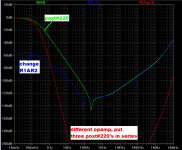
Simulation gives a flavor of what might be approximately possible. Do you get the impression that (three greens in series) might not be as good as (one blue in series with two greens) ??
_
I was unsure to begin with but you are probably right. What were the changes to R1 & R2?
I have gone back to basics in terms of layout and wiring. For example the leads from the bench PS to the prototype module were almost 1 ohm. The layout was shambolic in some respects too. To give a clearer picture the prototype module is a plastic box with two 1660 hole breadboards attached. There are also several binding posts and also 2 BNC sockets for connecting to certain test equipment. There were 3 4mm sockets for incoming power from the bench PS and these were routed internally to the power rails of the breadboards.
I have so far made the following improvements:
1. Better leads between The power supply and the module. ( Shorter and thicker, hence < resistance, now about 0.2 ohms )
2. Doubling up the internal power rail connections in the module.
3. Have included Mark's suggested pre load resistors of 1K2 across the +ve rail and ground and 500R between -ve rail and ground.
3. A comprehensive star ground arrangement to permit every part of the setup to be returned to one central point, which itself is connected to the ground of my signal generator which is internally connected to mains earth.
Before utilizing any of the more elaborate ideas discussed in posts #209 thru #222, I am going to implement these basic changes that can only better any subsequent circuitry for cleaning up the rails.
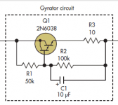
Returning to the circuit in post #220 I was wondering about a gyrator circuit in place of the resistors, see attachment which is equivalent to a 5H inductor, I'm not sure about the DC voltage drop though if using this.
Attachments
Last edited:
Quick update: To make things a lot simpler regarding power supply requirements I decided to power the amplifier from batteries, that way the inputs can be floating and likewise the output that will be connected to a battery operated DMM.
Initially I had a bit of trouble with the amplifier oscillating at around 1 MHz when powered by 2 9 volt batteries. It was necessary to improve local decoupling and change the layout a bit. I'm guessing that the problem may have been related to the relatively high internal resistance of the power source, anyway it's fixed now. I was a bit dissapointed with the noise output by the ne5532 even with the ultra clean supply ( batteries and lots of decoupling ) just for fun I tried a tl072 and the noise was about the same! Note that I had the +ve input connected straight to ground, so it wasn't noise from the input bias resistor. I tried several opamps in the end the best result was with an lm833. I'm starting to wonder if the 5532's were fakes as I think they were bought on eBay.
Don't know how long the pp3 9v batteries will last with a drain of 4.26mA, I thought of using the lm358 as it only draws 500uA per 1/2 though the equivalent input noise is dire at 55nV/√Hz!
Any good suggestions for a quiet but low power opamp would be gratefully received.
Gordon.
Last edited:
This looks like a good candidate:
LT1037 - Low Noise, High Speed Precision Operational Amplifiers - Linear Technology
LT1037 - Low Noise, High Speed Precision Operational Amplifiers - Linear Technology
Hi, Just wanted to assure any followers that I've not given up on this venture!
In fact I've become quite obsessed with perfecting my setup for measuring current source impedance. Over the last week I have tried numerous options in terms of finding a suitably sensitive (high gain) amplifier with the minimum of noise pick up. So far I've come to the following conclusions;
(I) The amp should have the lowest noise possible.
In this respect the LM833 has yielded the best results. I was dissapointed with the INA131 instrumentation amplifier in this respect, though most of the noise generated was in the < 10 Hz realm and could be tamed with subsequent High Pass Filtering.
(ii) Preferably the input should be differential to avoid issues with ground loops and / or power supply noise. ( That is, the power supply that feeds the CCS not the one that feeds the amplifier itself. )
Maximum CMR is essential here and I tried using an INA131 instrumentation amplifier which was good in respect of CMR but a lot noisier than the LM833 based differential amplifier.
I have decided to limit testing to 1KHz +, as impedance below 1khz is typically similar to DC results. I will therefore be introducing a High Pass Filter in the signal chain. I am thinking of introducing an optional Low Pass Filter to limit the bandwidth at the high end too to maximize noise reduction and recovery of a clean signal for subsequent measurement.
(iii) Ideally it would be powered from a perfect source.
Batteries would be ideal but are prohibitively expensive. I have a separate 2 x 12volt power supply that I built years ago before I got the bench PS, I shall be using this and keep the grounds separate. In practice the use of a battery supply in comparison to the 2x12 volt supply didn't make a measurable difference to the output noise level probably due to the excellent PSRR of the opamps. Combined with the differential input this should keep out bench PS noise and back fed test signal via the power rails ( that is the CCS power rails ) I have utilized the pre load resistors suggested by Mark Johnson along with lots of local decoupling capacitors, both electrolytic and ceramic.
In addition to the amplifier. I intend to utilize a precision rectifier at the output to circumvent any problems with the bandwidth of my DVM's.
I have kept written records of all my experiments that brought me to the aforementioned conclusions, but I didn't wish to bore anyone with the details! 🙂
Gordon.
Last edited:
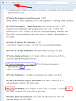
Thats off by 13% at 20 kHZ. Try to get a hp3478a or hp3447a at ebay - they are very good and reasonable priced. Other option is to add a peak detector at the output and measure the DC voltage.
Thanks Udo, The HP3478A looks like very good value, I was expecting this sort of meter to be £500+ ($750+), I was pleasantly surprised. No one selling on eBay UK just now, but I'll keep a look out for one.
For anyone else interested:
ROBOT WARNING - at the Test Equipment Depot
Gordon. 🙂
Thanks Mark, Problem for me in the UK is shipping and import taxation!
Though I'm sure many of our American members will benefit from this information.
Gordon.
Though I'm sure many of our American members will benefit from this information.
Gordon.
Regarding power supply noise, this is the sort of thing I've been troubled with:
See Attachment.
This is not an actual photograph of the spikes I've been seeing but is close enough. The horizontal scale is about 1uS, making the pulses a little under 1MHz. They are regular but both aperiodic and of variable height ( amplitude ).
Combinations of capacitors and a simulated inductor ( gyrator based ) produced no visible difference, but the same noise is apparently being picked up by my 'scopes leads and makes viewing of small signals <5mV peak difficult. Does anyone have any suggestions as to; (i) Where these spikes are coming from, my first thought was a switching power supply but there were none in the vicinity. I also thought about my home wireless network, could it be that? (ii) How to defeat this noise / interference?
Gordon.
Attachments

Quick update: I found some precision 0.1% resistors on Saturday when sorting my components......was actually looking for something else...but this was a good find! I intend to build a low noise instrumentation amplifier with two lm833's and my precision resistors. Assuming this is successful I will get back to the task in hand, namely; measuring the impedance of different current sources. 🙂
A lesson hard learned: Never underestimate the undesirable effects of capacitive coupling with breadboards!
Only 0.4pF doesn't sound like much, but when you're trying to measure 10M+ at 20KHz it starts to become a real nuisance!
Gordon.
____________
For reasons I can't fathom I couldn't get my homebrew differential amplifier to work. I've gone back to a single ended amplifier made with two halves of an lm833 powered by an independent +/- 12 volt power supply along with lots of due care and attention to layout and construction.
Should be publishing some more results within the next week. By necessity I've been forced to put this project at a lower priority than other more pressing matters.
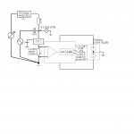
BLOCK DIAGRAM OF LATEST SETUP ATTACHED.
Notes: The HPF is to tame sub 10 Hz noise which is quite significant in a x5000 amplifier. I've also built a little RMS to DC circuit to get round the upper measurement frequency limitation of my portable DMM's.
Only 0.4pF doesn't sound like much, but when you're trying to measure 10M+ at 20KHz it starts to become a real nuisance!
Gordon.
____________
For reasons I can't fathom I couldn't get my homebrew differential amplifier to work. I've gone back to a single ended amplifier made with two halves of an lm833 powered by an independent +/- 12 volt power supply along with lots of due care and attention to layout and construction.
Should be publishing some more results within the next week. By necessity I've been forced to put this project at a lower priority than other more pressing matters.
BLOCK DIAGRAM OF LATEST SETUP ATTACHED.
Notes: The HPF is to tame sub 10 Hz noise which is quite significant in a x5000 amplifier. I've also built a little RMS to DC circuit to get round the upper measurement frequency limitation of my portable DMM's.
Attachments

Last edited:
I have posted my precision rectifier circuit I'll be using in the all other topics section:
http://www.diyaudio.com/forums/everything-else/274754-ca3240-based-precision-rectifier.html
Gordon.
http://www.diyaudio.com/forums/everything-else/274754-ca3240-based-precision-rectifier.html
Gordon.
For anyone who has been following this thread in the hope of seeing some results my lack of progress must be frustrating. About 3 or 4 weeks ago I embarked on a mission to sort out my components, something I've been meaning to do now for a few years. It is taking longer than expected as I've been cataloging my stocks as well as selling off some of the surplus on eBay, I am moving closer to completion and yesterday I came upon a telephone transformer I had bought on eBay years ago. This made me think about Elvees idea of using a transformer in the CCS impedance measurement setup.
I was looking back over the thread today and came up with the attached idea. Essentially the transformer would be getting used as a current transformer and with the low input impedance of the trans impedance amplifier any capacitive coupling across the transformer would be severely attenuated.
I need to try this to see how well it works in practice, the simulator I have on my Android tablet is fairly basic and doesn't take into account some of the more subtle effects.
Attachments

The circuit in post#235 looks like it will pass DC current through the primary of the transformer. Will that saturate the core? Will it add extra distortion?
The circuit in post#235 looks like it will pass DC current through the primary of the transformer. Will that saturate the core? Will it add extra distortion?
You are correct, I will need to try it. I'm assuming that it might tolerate the relatively small 5 MA as in its original function as a telephone transformer there would have been a small DC current present in use with the speech signal riding on top of it.
Looks like the pulses of a switched mode power supply. What is the frequency of the pulses?.
If you decide to get the HP Meter, get a HP laboratory power supply too.
(Have a look at the HP catalogs from 1980-1990).
If you decide to get the HP Meter, get a HP laboratory power supply too.
(Have a look at the HP catalogs from 1980-1990).
Regarding power supply noise, this is the sort of thing I've been troubled with:
See Attachment.
This is not an actual photograph of the spikes I've been seeing but is close enough. The horizontal scale is about 1uS, making the pulses a little under 1MHz. They are regular but both aperiodic and of variable height ( amplitude ).
Combinations of capacitors and a simulated inductor ( gyrator based ) produced no visible difference, but the same noise is apparently being picked up by my 'scopes leads and makes viewing of small signals <5mV peak difficult. Does anyone have any suggestions as to; (i) Where these spikes are coming from, my first thought was a switching power supply but there were none in the vicinity. I also thought about my home wireless network, could it be that? (ii) How to defeat this noise / interference?
Gordon.
Hi Gasboss775!
Some time ago (enough to paper got yellow 🙂) I solved the same question and I'd like to share with results obtained (see please the application).
I measured the output resistance of the elementary stage with common emitter (the finding collector resistance of the transistor is approximately the product of the stage gain and that measured resistance). For these purpose in the collector circuit was introduced two resistors, the first (Rk2=680 om) - to provide the alternative collector voltage, the second (Rk1=1 kom) - to provide the measurement of the collector current deviation, caused by that voltage.
A lot of Soviet and World brand transistors were examined (even some FETs).
Instead of low frequency generator (Soviet G3-118 in my case) pulse measuring generator also can be used (no matter how to change the collector voltage).
The connection of ground terminals of measuring devices, as shown on the drafts, turned out good enough to provide tolerable noise level.


With respect, Igor Shukov
Some time ago (enough to paper got yellow 🙂) I solved the same question and I'd like to share with results obtained (see please the application).
I measured the output resistance of the elementary stage with common emitter (the finding collector resistance of the transistor is approximately the product of the stage gain and that measured resistance). For these purpose in the collector circuit was introduced two resistors, the first (Rk2=680 om) - to provide the alternative collector voltage, the second (Rk1=1 kom) - to provide the measurement of the collector current deviation, caused by that voltage.
A lot of Soviet and World brand transistors were examined (even some FETs).
Instead of low frequency generator (Soviet G3-118 in my case) pulse measuring generator also can be used (no matter how to change the collector voltage).
The connection of ground terminals of measuring devices, as shown on the drafts, turned out good enough to provide tolerable noise level.
With respect, Igor Shukov
Looks like the pulses of a switched mode power supply. What is the frequency of the pulses?.
If you decide to get the HP Meter, get a HP laboratory power supply too.
(Have a look at the HP catalogs from 1980-1990).
The pulses aren't coming from the bench PS, as I've used a linear one ( that I built previously ) and the noise pulses are still present. Perhaps the pulses are present in the ac power line from other equipment in the house with switching power supplies. The pulses are not at a fixed frequency, which is puzzling.
I will check out the HP power supplies.
___________________________________________
Hi Gasboss775!
Some time ago (enough to paper got yellow 🙂) I solved the same question and I'd like to share with results obtained.....
Thank you very much Shukov for sharing your results. 🙂
You have given me fresh encouragement to carry on with this project! At the moment I am away on holiday / vacation though I intend to get back to the task when I return home. One question, what did you use to measure the voltage across the 1k resistor?
Gordon
Last edited:
- Status
- Not open for further replies.
- Home
- Amplifiers
- Solid State
- How do you calculate impedance of a current source?