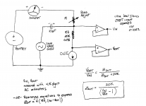
An alternative setup is shown below. It eliminates the need for a negative power supply, and measures large signals (2V p-p) without the need for high gain, low noise amplifiers. However it does require you to subtract two AC voltages that are very close together. If the Device Under Test's output impedance is 5 megohms, then (Vin/Vout) = 1.004, so do you need to measure Vin and Vout to at least 4.5 digits of accuracy, or better.
Richard C. Jaeger's 1974 article "A High Output Resistance Current Source" (citation) claims that he built a 3-transistor Wilson current source using semi-matched transistors from a CA-3086 integrated circuit (datasheet) and got an output impedance of 3.5 Megohms. I figured that 41 years later we'd at least be approaching 5 Megohms if not better. Jaeger does not disclose his testing apparatus setup, he merely reports the measured impedance as a single scalar, presumably at DC.
_
Attachments
Mark, I presume the ca3240 would be usable in your suggested circuit or would input capacitance be a problem?
One of us will need to do some hand calculations or some LTSPICE simulations. That will provide the opportunity to also re-consider the value of R2 and the voltage drop (Idut * R2), which is relevant to the choice of adjustable DC power supply.
One of us will need to do some hand calculations or some LTSPICE simulations. That will provide the opportunity to also re-consider the value of R2 and the voltage drop (Idut * R2), which is relevant to the choice of adjustable DC power supply.
I had been thinking for awhile now, that trying to measure a 5mA CCS was perhaps not the best way as it involves quite a low ( 1K ) current sensing resistor to keep the DC voltages sensible. If we were to instead examine say, 500 microamp CCS's then a 20K resistor would involve a manageable 10 volt drop at DC and provide a reasonably large measurable ac signal as you've suggested.
Actually the biggest problem I was faced with during my last efforts was stray ac coupling ( probably capacitive ) through the breadboard upon which the CCS under test was assembled, I will need to look at other construction techniques.
I now need to go look at the ca3240 input capacitance!
Gordon.
The ca3240 would be unusable in this configuration due to its 44pFinput capacitance. The LT 1022 is better at 4pF. I'd prefer to measure the ac voltage due to the CCS' impedance on the low side of the ccs as the amplifier / buffers input Z will have much less effect on the measured result.
One question, what did you use to measure the voltage across the 1k resistor?
Hi Gordon!
I applied ancient Soviet oscilloscope (on transistors, not lamps🙂) C1-99. The only significant for the tests was it's voltage measuring range - up to 2 mv/dev. Been turned in low bandwidth mood it permitted easy measurements on sine signal.
I can add only, in the place I'm sitting fake components are rather a problem, it's the life urges you to perform that and other interesting tests😱.
Nice weather and good vacation,
Igor
One question, what did you use to measure the voltage across the 1k resistor?
Hi Gordon!
I applied ancient Soviet oscilloscope (on transistors, not lamps🙂) C1-99. The only significant for the tests was it's voltage measuring range - up to 2 mv/dev. Been turned in low bandwidth mood it permitted easy measurements on sine signal.
I can add only, in the place I'm sitting fake components are rather a problem, it's the life urges you to perform that and other interesting tests😱.
Nice weather and good vacation,
Igor
Hi Igor,
I have tried various methods, these are documented earlier in this thread. I have messed around trying to refine the technique. My oscilloscope isn't very good, it's a cheap modern digital instrument and on its most sensitive range ( 5mV / div ) the intrinsic noise in the Y amplifier makes useful measurements difficult. A low noise preamplifier has been employed and either the scope ( on a less sensitive range; 0.5 ~ 2 V / div ) or my 4.5 digit DVM measuring AC volts has been used.
This, was probably my preferred setup, see below:
Though I will probably power the opamp with a separate +/- 12 volts supply.
Also; fake components are a nuisance, eBay is really bad for it. But I've heard of reputable suppliers selling fakes too.
Thanks Igor,
I will be returning home tommorow.
Last edited:
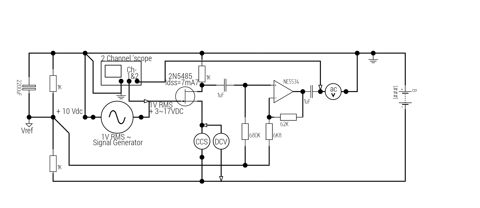
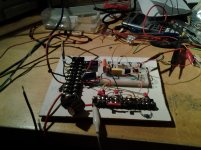
Have had a bit of spare time over the last few days and put together a new test rig for CCS impedance measurements. The actual CCS is assembled on a small terminal block ( at the front of the attached image ) to try and get round the problem of capacitive coupling when it is assembled on a breadboard.
Initial result was surprising, using a 500 microamp 2 transistor CCS with 2 x BC549C both with hFE around 530. At 1 KHz impedance was around 41 Megohms. Still to test at 5 & 10 KHz. Will post more later.
Schematic and Photo of rig attached.
Initial result was surprising, using a 500 microamp 2 transistor CCS with 2 x BC549C both with hFE around 530. At 1 KHz impedance was around 41 Megohms. Still to test at 5 & 10 KHz. Will post more later.
Schematic and Photo of rig attached.
Attachments
IC2 output is DC coupled. Thus it includes a DC component equal to IC1's input offset voltage (6 mV) times (1+(R6/R7)) ... 606mV. Plus IC2's input offset voltage. Plus IC1's input current offset, times 37K, times the gain of IC1 ... 373mV.
Maybe the 4.5 digit meter rejects DC?
Maybe the 4.5 digit meter rejects DC?
IC2 output is DC coupled. Thus it includes a DC component equal to IC1's input offset voltage (6 mV) times (1+(R6/R7)) ... 606mV. Plus IC2's input offset voltage. Plus IC1's input current offset, times 37K, times the gain of IC1 ... 373mV.
Maybe the 4.5 digit meter rejects DC?
I've just realized from your comment that there is an error in the schematic. The bottom of R7 should go to ground via a 2.2uF capacitor such that the DC gain is only 1 to minimize the effects of input offset effects. IC1's input current is in the picoamp realm surely and thus pretty insignificant overall. There will be still a small DC offset and at the voltages being measured could result in a significant error ( if the meter calculates the RMS value of the DC and ac components. ) I will add a capacitor and see if there's a difference.
Thanks for pointing that out.
Gordon.
That's nothing that a capacitor in series with R7 (or an additional coupling cap) couldn't fix though.IC2 output is DC coupled. Thus it includes a DC component equal to IC1's input offset voltage (6 mV) times (1+(R6/R7)) ... 606mV. Plus IC2's input offset voltage. Plus IC1's input current offset, times 37K, times the gain of IC1 ... 373mV.
EDIT: Too slow...
BTW - if mains hum is such a problem, it may be better to split the gain between IC1/IC2. A TL07x at +40 dB isn't exactly going to be the epitome of linearity and bandwidth (about 30 kHz, -6 dB). When it comes to highish source impedances, low-Ib bipolar OPs tend to be worth a try, too (their nonlinear input capacitance tends to be much smaller than in JFET input parts). Couldn't name any single ones aside from the trusty µA741, but NJM4565 or NJM4556A or NJM4560 or BA4560 ought to be quite good. (NE553x also are but obviously have much higher Ib.)
Oh, and how any of this even remotely works without any kind of shielding is beyond me. It's hardly surprising that a 50 Hz notch is needed. Ideally one would put the whole shebang into a big metal box at circuit ground potential. Big because you want to keep the circuit well away from its walls and resulting capacitive coupling. You probably won't be chancing upon a big diecast Al box any day, but I imagine some kitchenware about to be discarded, spare metal shields or even metal foil of one kind or another with a bit of creativity may prove helpful.
Last edited:
... 2 transistor CCS with 2 x BC549C both with hFE around 530. At 1 KHz impedance was around 41 Megohms.
That does sound surprising; I would have expected the impedance to be a factor of ~ twenty smaller.
You can calibrate your apparatus by connecting branches with known impedance, in parallel with your current source. See attachment.
With Rx = 1 megohm, you would expect to measure (41 || 1) = 0.976 megohms with the parallel branch installed. And with Rx = 22 megohms you would expect to measure (41 || 22) = 14.3 megohms with the parallel branch installed. But if your apparatus gives different values, it casts doubt upon the original 41 megohm result.
In fact if you make a scatter plot of (known Rx value) on the horizontal axis, and (apparatus measured impedance of Rx parallel Zout_CCS) on the vertical axis, you could perform a least squares curve fit to numerically extract the Zout_CCS value which best matches all of the measured datapoints. Smells like science! Use 4 or 8 resistance values per decade, from Rx=0.5 Meg to Rx=50 Meg.
Edit- with Rx=10K and Cseries=100uF, there's a pole at 0.16 Hz ... well below the lowest frequency at which you might measure CCS impedance. Larger values of Rx move the pole to even lower frequencies.
_
Attachments

Last edited:
It depends very much on the set current (it is in fact inversely proportional).That does sound surprising; I would have expected the impedance to be a factor of ~ twenty smaller.
I made some measurements here, that was for 5mA IIRC:
http://www.diyaudio.com/forums/soli...-impedance-current-source-18.html#post4309378
I arrived at 14 meg, for 5mA current (for 1.5mA, 40meg would be about right). That is the magnitude; depending on the way the impedance is presented, the real part could be somewhat higher
Last edited:
That's nothing that a capacitor in series with R7 (or an additional coupling cap) couldn't fix though.
EDIT: Too slow...
BTW - if mains hum is such a problem, it may be better to split the gain between IC1/IC2. A TL07x at +40 dB isn't exactly going to be the epitome of linearity and bandwidth (about 30 kHz, -6 dB). When it comes to highish source impedances, low-Ib bipolar OPs tend to be worth a try, too (their nonlinear input capacitance tends to be much smaller than in JFET input parts). Couldn't name any single ones aside from the trusty µA741, but NJM4565 or NJM4556A or NJM4560 or BA4560 ought to be quite good. (NE553x also are but obviously have much higher Ib.)
Oh, and how any of this even remotely works without any kind of shielding is beyond me. It's hardly surprising that a 50 Hz notch is needed. Ideally one would put the whole shebang into a big metal box at circuit ground potential. Big because you want to keep the circuit well away from its walls and resulting capacitive coupling. You probably won't be chancing upon a big diecast Al box any day, but I imagine some kitchenware about to be discarded, spare metal shields or even metal foil of one kind or another with a bit of creativity may prove helpful.
Thanks for your advice. The construction of the CCS on a terminal block as opposed to on the breadboard was a deliberate step to reduce capacitive coupling. In addition I have connected two of the terminal block sections to ground in areas where the input signal is physically close to the output side of the CCS, to act as a shield to capacitive coupling.
It would seem that the effect of undue capacitive coupling would in fact be to reduce the calculated value of impedance as the impedance is inversely proportional to the output voltage. With a 10M 5% resistor, I got 10.8M with this setup.
Mark Johnson wrote:
In fact if you make a scatter plot of (known Rx value) on the horizontal axis, and (apparatus measured impedance of Rx parallel Zout_CCS) on the vertical axis, you could perform a least squares curve fit to numerically extract the Zout_CCS value which best matches all of the measured datapoints. Smells like science! Use 4 or 8 resistance values per decade, from Rx=0.5 Meg to Rx=50 Meg.
I'm not entirely familiar with this technique, can you elaborate?
I have corrected for the small DC component at the output with a coupling capacitor. ( it was influencing the measured value ) I have also measured amplifier gain at all the test frequencies used and plugged these into the impedance calculation. Overall gain varied by < 1 dB.
These are the results, again with the same CCS using 2x bc549c, using Zccs = Vin / ((Vout/Gain)/R5||R6)
Freq. Vi . Vout. Gain. Impedance.
1K. 1.0074. 0.0173. 104.23 50.05M
2K. 1.0074. 0.0189 107.81. 47.38M
5K. 1.0073. 0.0478. 106.67. 18.54M
10K. 1.0071. 0.0914. 99.55. 9.04M
EDIT: I forgot to include the DC conditions; I ccs (DC) = 0.5mA, V ccs (dc) = 24V5 - 8V8 = 15V7.
Last edited:
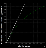
In fact if you make a scatter plot of (known Rx value) on the horizontal axis, and (apparatus measured impedance of Rx parallel Zout_CCS) on the vertical axis ...
Here is an example of what the scatter plot might look like. On the horizontal axis is Rx, the external resistor (+ 100uF cap) placed in parallel with the CCS under test. On the vertical axis is the impedance measurement obtained from the test apparatus.
The green curve shows what the data would look like if the CCS impedance were exactly 41 megohms.
The white curve shows what the data would look like if the CCS impedance were infinity. (remember that (Rx parallel Infinity) is simply Rx).
Attachments
Thanks Mark,
No more results yet, just wanted to give a taster of my intentions with this project.
First off I'm not going to mess about with the measurement setup anymore, I'm looking to make comparisons rather than find exact measurements, I'm happy with what I've got so far.
Next thing I plan on doing is trying the same 2 x bc549c CCS with different DC current values, probably; 0.5, 1, 2 & 5 MA at frequencies of 1, 2, 5 & 10KHz, to try to verify experimentally that CCS impedance is inversely proportional to DC current.
After that I intend to test the 1 BJT & LED type CCS, then the BJT/LED one with a cascode transistor, also I will try a few jfets to see how they fair as current sources.
If anyone has any special requests, I will try to oblidge if I'm able to.
Presumably the Imaginary part is due to capacitance?
EDIT: Does the DC voltage across a CCS affect its impedance? Is this worth investigating?
Gordon.
No more results yet, just wanted to give a taster of my intentions with this project.
First off I'm not going to mess about with the measurement setup anymore, I'm looking to make comparisons rather than find exact measurements, I'm happy with what I've got so far.
Next thing I plan on doing is trying the same 2 x bc549c CCS with different DC current values, probably; 0.5, 1, 2 & 5 MA at frequencies of 1, 2, 5 & 10KHz, to try to verify experimentally that CCS impedance is inversely proportional to DC current.
After that I intend to test the 1 BJT & LED type CCS, then the BJT/LED one with a cascode transistor, also I will try a few jfets to see how they fair as current sources.
If anyone has any special requests, I will try to oblidge if I'm able to.
I arrived at 14 meg, for 5mA current (for 1.5mA, 40meg would be about right). That is the magnitude; depending on the way the impedance is presented, the real part could be somewhat higher
Presumably the Imaginary part is due to capacitance?
EDIT: Does the DC voltage across a CCS affect its impedance? Is this worth investigating?
Gordon.
Last edited:
Have you tested your measurement setup with some high valued resistors?
Maybe 100 k, 1 Meg, 10 Meg 100 Meg?
You put a lot of work in this.... better to be sure that the setup is right.
Maybe 100 k, 1 Meg, 10 Meg 100 Meg?
You put a lot of work in this.... better to be sure that the setup is right.
Have you tested your measurement setup with some high valued resistors?
Maybe 100 k, 1 Meg, 10 Meg 100 Meg?
You put a lot of work in this.... better to be sure that the setup is right.
I will try this. Largest resistors I have are 10 meg, I suppose I could make bigger resistors by connecting 10 meg resistors in series.
Gordon.
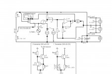
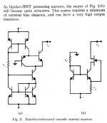
Maybe you will want to try out Richard Jaeger's "High Output Resistance" current source Fig 3(b) to see if it's as good as he says.
(link)
I checked DigiKey this morning for suitable Nchannel JFETs in thru-hole packages. I found that DigiKey has several of them, in stock and on the shelf, today: J107, J109, J111, PN4391. You want (Idss >= 20mA); bigger is just fine because the circuit will autoadjust by changing the Vgs bias point to give the 2mA or 5mA current you have chosen. And your tester puts a huge voltage across the current source (about 10V!) so you can use FETs with huge Idss if you wish. Shoot even the J105 with Idss=500mA would work. Of course you open the door to many more possible partnumbers if you allow yourself to use NJFETs in surface mount packages.
Play with it in the simulator. Select component values that are well-centered for high yield over parameter variations (tolerances), and try out the circuit in your tester. Maybe Jaeger was right, maybe it's awfully good.
_
Attachments
Last edited:
- Status
- Not open for further replies.
- Home
- Amplifiers
- Solid State
- How do you calculate impedance of a current source?