Okay, here's what I did, that led up to a "no save" - I scrolled to an existing file, hit add, and loaded in a new driver (from the driver database) and then edited a number of things in the Loudspeaker Wizard: changed the last two sections, changed the L12 path length, changed the fill values, Saved the changes. I opened Loudspeaker Wizard at least 4 times and saved it each time.
I did a couple of screen captures, and toggled over to my image editor (IrfanView), and toggled back and forth to DataCAD several times. I saved a PDF from DataCAD, and then a screen capture from the PDF. I toggled a couple of times also with Firefox, to post things on the Facebook Transmission Line group.
I exported the file, to be able to reload what I had done, for our friend Justin Case.
When I then clicked Previous in Hornresp, it did not ask be to save the record.
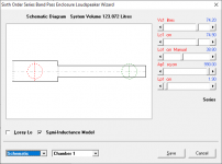
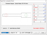
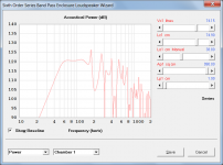
Another comparison that might be of interest - this time it's a design sim'd as a series-tuned BP system and then as a TH. The differences are not as pronounced as my last comparison, but they're still there. Fb in the BP sim is a few Hz lower than that of the TH sim.
So, which one is "more correct" 🙂
The workbook is BOXPLAN-BP6S2 v 0.3 beta, available from my site The Subwoofer DIY Page - Horn Folding
So, which one is "more correct" 🙂
The workbook is BOXPLAN-BP6S2 v 0.3 beta, available from my site The Subwoofer DIY Page - Horn Folding
Attachments

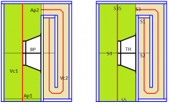

Heres a good one for the experimental people out there
?? .The folding not expressed entirely in this sim changes the top of bandwidth (ie: the Fb/3 ‘void’ is hard to distinguish, if even there at all?). Ill get a proper measurement for this shortly, but dropped the dats into a long vent on an awkward and heavy subwoofer. 🙁
Seems that void is remedied in this Or it can be exploited and become a ripple or bulge. in previous experiments i used 6 or 5 folds and the effect was questionable or lost in the excess of design chambers, port, etc. but this is pretty straight forward and even the offset is inside the useful assumption of the lengths and direct radiator/exit position is nearly zero.
Taking this further is tricky but i wonder if the offset driver position is the only tool In horn response that is representative of this affect? If tapped can be used to look (in sim) for techniques like this which arent otherwise seen because theyre specific to ‘folding’?
Attachments

if it happens again, I'll try to reproduce the issue as the steps I took would be a bit fresher in my mind.
Many thanks Brian. This is starting to frustrate the life out of me! There is obviously a subtle bug somewhere, but do you think I can trigger it - no way. I am taking heed of all the feedback, and trying everything I can think of, but without success so far! I hate these sorts of "intermittent" problems (the worst possible kind), and will certainly keep looking for the cause...
I have different scenario that it didn't prompts to save, it's as follows
Hi 1hiep0,
Thanks for the feedback, and for providing a complete sequence of actions.
In your case everything is working as it should. If a change is made in the Loudspeaker Wizard and the Cancel button rather than the Save button is clicked to close the wizard, then any changes made in the wizard are not saved back to the main screen. Because no changes have been made to the main record, there is no need for the Save message to appear when Hornresp is closed.
If however the Save button rather than the Cancel button is clicked in the wizard, then the Save message should definitely appear when Hornresp is closed.
Kind regards,
David
Hi Eric,
Clicking the Add button simply adds a copy of the current record to the end of the data file as a new record. The new record is then normally edited to suit the particular design to be simulated, and the changes then saved before switching to a different record or closing the program. If the changes are not saved, then the new record will simply be retained as a copy of the original record.
"Save" is a different operation to "Add" - Save permanently saves any changes made to a record to the data file.
Kind regards,
David
Does "add" mean "start a new record" or "add the current record to the saved file in its current state?
Clicking the Add button simply adds a copy of the current record to the end of the data file as a new record. The new record is then normally edited to suit the particular design to be simulated, and the changes then saved before switching to a different record or closing the program. If the changes are not saved, then the new record will simply be retained as a copy of the original record.
So "add" is what's supposed to "save"?
"Save" is a different operation to "Add" - Save permanently saves any changes made to a record to the data file.
Kind regards,
David
Okay, here's what I did, that led up to a "no save"
Many thanks Neil. I tried to replicate your sequence of actions as closely as I could, but still no luck - the "Save changes to current record?" message appeared as it should when I clicked the Previous button. I am not going to give up just yet though - there must be a reason for the problem, it's simply a matter of finding out what it is... 🙂.
How to model compound horn w/offset
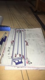
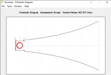
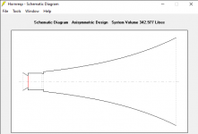
I'm working on a compound horn which has an offset driver horn as Horn 1, and a simple short exp horn as Horn 2. See the design image. Two questions...
1. I can specify the first schematic in Hornresp, but a more accurate depiction would be the second (photoshopped) schematic. Can this be modeled? Does it matter?
2. I'm modeling a with a full range driver (~6.5" diameter), but Hornresp always shows a rolloff above 1kHz--is that just because it's treated as a woofer, and I shouldn't worry about it?
Attachments
Not an expert here by any means as I am just learning my way through it, but could your roll-off be from not using semi-inductance in the driver parameters?
Not an expert here by any means as I am just learning my way through it, but could your roll-off be from not using semi-inductance in the driver parameters?
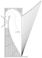
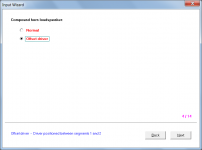
Learning my way through this too! And accordingly, I don't really know what you mean. Can you elaborate? Attached are the input parameters as presently set, awaiting an answer to Q1. Ignoring the horn parameters, you can see the driver parameters, if that helps.
Attachments

The Le parameter can be set with three different methods. First is just the Le number we get from the spec sheet or our DATs. Then if you double click on the Le icon, it will turn red meaning "lossy inductor". Then there is the more advanced semi-inductance parameters on data entry as Le is not linear in a speaker. ( Icon wil be green) GOOGLE semi-inductance.
Semi-Le_Calc: Calculator for Advanced Inductance Model Incorporating Semi-Inductance
I have not got it to work yet as I get a variable out of range error on import.
Semi-Le_Calc: Calculator for Advanced Inductance Model Incorporating Semi-Inductance
I have not got it to work yet as I get a variable out of range error on import.
The Le parameter can be set with three different methods. First is just the Le number we get from the spec sheet or our DATs. Then if you double click on the Le icon, it will turn red meaning "lossy inductor". Then there is the more advanced semi-inductance parameters on data entry as Le is not linear in a speaker. ( Icon wil be green) GOOGLE semi-inductance.
Thanks very much for this. Did some reading, downloaded the spreadsheet, and the manufacturer does actually provide the impedance data in an importable file. Loaded the parameters into Le (green), and the SPL did rise a bit above 1kHz, but still rolling off dramatically compared with the manufacturer's freq response. Still wondering...
a more accurate depiction would be the second (photoshopped) schematic. Can this be modeled? Does it matter?
It can be modelled using the CH1 option, and it does matter. Use the Input Wizard to specify the required configuration.
I'm modeling a with a full range driver (~6.5" diameter), but Hornresp always shows a rolloff above 1kHz
As indicate in the Help file, the driver diaphragm is modelled as a rigid plane circular piston. A full range driver will not be operating as a rigid piston at the higher frequencies.
Attachments
So, which one is "more correct" 🙂
The TH model is more correct because port tubes (and their associated end corrections) are not really applicable to the design being simulated.
If the physical dimensions are specified exactly the same for both systems (they are not all the same in your given examples) and the BP6S port tube end corrections are removed, then reassuringly, the results become identical, as shown in the attachments.
Attachments

If a change is made in the Loudspeaker Wizard and the Cancel button rather than the Save button is clicked to close the wizard, then any changes made in the wizard are not saved back to the main screen. Because no changes have been made to the main record, there is no need for the Save message to appear when Hornresp is closed.
1hiep0 - my apologies, I had not read your post carefully enough. I missed the critical point that the change to S1 was made prior to opening the loudspeaker wizard, rather than by adjusting the slider in the wizard itself. You have indeed identified a problem.
Many thanks for the feedback!
Last edited:
#1 Manufactures specs are advertising
#2 Specs help you decide to buy. You need to measure for real. Prototype, measure and refine.
#3 look carefully as the graph and the vertical scale. It may not be rolling off as steep as it looks. What looks like a brick wall is only about 6 dB/octave
Now, if I could get the spreadsheet to accept my .zma file. Wondering it is the "+" signs.
It can be modelled using the CH1 option, and it does matter. Use the Input Wizard to specify the required configuration.
[...]
As indicate in the Help file, the driver diaphragm is modelled as a rigid plane circular piston. A full range driver will not be operating as a rigid piston at the higher frequencies.
Thank you! I have read that part of the documentation, just didn't understand its implications for an FR driver's SPL response, thanks.
"Subscript out of range"
I removed the header, Removed the + signs. No help.
Another file, tweeter actually" says "not enough columns, yet it has all three.
There must be some restrictions on this import file I am not aware of.
This is the Excel worksheet to extract semi-inductance for loading into HR.
I removed the header, Removed the + signs. No help.
Another file, tweeter actually" says "not enough columns, yet it has all three.
There must be some restrictions on this import file I am not aware of.
This is the Excel worksheet to extract semi-inductance for loading into HR.
"Subscript out of range"
I removed the header, Removed the + signs. No help.
Another file, tweeter actually" says "not enough columns, yet it has all three.
This is the Excel worksheet to extract semi-inductance for loading into HR.
FWIW, here's a .zma file that worked for me with the latest version of the spreadsheet in Excel v2012m if you want to test with it...
[if this forum platform doesn't expose the uploaded file, you can find it as part of a zip file here: Dayton Audio - PS180-8 6-1/2" Point Source Full-Range Neo Driver
Last edited:
- Home
- Loudspeakers
- Subwoofers
- Hornresp