You might be interested in the Speaker Crossover document I wrote about 10 years ago. It shows the various crossover topologies you're talking about here such as first-order with notch filters and higher-orders with R/R/C networks for mass-rolloff compensation. That way, you can compare and contrast the advantages and disadvantages of each topology.
I wrote this documents specifically about crossovers used with speakers that incorporate constant directivity horns needing top-octave compensation for mass rolloff. It is an exploration and description of each circuit type using Spice to model the networks and show the transfer function of each one. It also shows the voltage/power across each component with a chart, showing voltage verses frequency.
I wrote this documents specifically about crossovers used with speakers that incorporate constant directivity horns needing top-octave compensation for mass rolloff. It is an exploration and description of each circuit type using Spice to model the networks and show the transfer function of each one. It also shows the voltage/power across each component with a chart, showing voltage verses frequency.
"Earl is going for an unknown acoustical response (maybe 3rd order, maybe 4th order)"
It was my impression that Earl doesn't care what order it is, as long as he gets smooth freq response and good polar behavior.
It was my impression that Earl doesn't care what order it is, as long as he gets smooth freq response and good polar behavior.
noah katz said:"Earl is going for an unknown acoustical response (maybe 3rd order, maybe 4th order)"
It was my impression that Earl doesn't care what order it is, as long as he gets smooth freq response and good polar behavior.
I heard him a bit differently. He doesn't care about the order of the electrical transfer function. What he cares about is the acoustical response of the individual drivers and the two combined, just like all good crossover designers. Maybe Earl will clarify it for us.
I've taken the position not to respond in this thread due to the disrespectful manner in which I was treated. If you want to ask the questions over at one of my other threads then I will respond. The sooner this thread dies the better.
Russellc said:Sure would like to see what those values are! Oh well.
russellc😕
I can't think of many loudspeaker designers who've published polar plots, the part numbers of their drivers, discussed the design extensively in public forums, etc...
He even published the crossover network online. None of this is a trade secret.
I could have easily built a "clone" of the Summa instead of buying it, but the finished speaker is less expensive than what it would cost for me to build it myself. (Factoring in a reasonable cost for my labor hours.)
From a reproduction device point of view, I think horn and waveguide are basically the same device. The mix of design tradeoffs can be whatever the designer wishes.
In a speaker with vertically stacked drivers, crossover slope (phase) has the most effect on the vertical polars, not horizontal. The horizontal polars are set by the size and directivity of the sound sources, their position on the baffle and the crossover frequency. So the crossover has very little to do with horizontal polars and everything to do with the verticals.
Now that's not to say summing isn't important on-axis or off-axis horizontally. It is important. But what I'm saying is that when drivers are stacked vertically, horizontal movement of the listener causes no change in path length difference between listener and sound sources. Because of this, the phase relationship between sound sources is pretty well contant as the listener moves along the horizontal. The end result is the crossover doesn't do much to set the horizontal polars, except with respect to crossover frequency. Whatever response is found on-axis is pretty much the same off-axis horizontally (at least in the pattern, the forward lobe) from a speaker using a CD horn, properly matched to its direct radiator.
The things that set the horizontal directivity are the horn and the woofer size. The horn sets the pattern up high and the woofer directivity is set by the frequency. Woofer directivity collapses as frequency rises, and the idea is to set the crossover frequency where the horn and woofer approximately match in the horizontal plane.
The vertical directivity is much more complex, because it involves path length differences between sound sources and crossover phase. That's what causes the vertical nulls to form. The careful designer sets the crossover to provide the best possible performance, setting the frequency for horizontal matching and the phase for best vertical performance.
I have also noticed that obliques can be set with careful crossover design and placement of sound sources. Normally, one wouldn't offset a tweeter one way or the other unless packaging required it. You would usually want the woofer and tweeter aligned vertically on the baffle. But I have found that slight offset modifies the obliques and even slightly modifies the verticals.
When the tweeter is shifted slightly (less than 1/4 wavelength) to one side in one of my models, the notch formed by the vertical null is made less deep directly above and below the speaker, as well as in the diagonal away from the tweeter shift. The deepest notch occurs along the line drawn between woofer and tweeter centers. This is what I would expect, but oddly, it shifts it much further with the rectangular horn I use. Instead of the notch being deepest directly on the line between driver centers, it is shifted way off to the side, in my case, all the way out to the diagonal edge. I suspect this has to do with the directivity of the HF horn and possibly an interaction with far off-axis side lobes.
The horizontal directivity of the midwoofer forms nulls and side lobes, but they are out-of-band in a properly designed speaker. They would occur in the vertical too, but they're much further out than the interference nulls, so are overshadowed by them. In a speaker with 90 degree pattern, if crossover is done where horizontal matches, then the woofer's side lobes are way out to the side. They come closer and closer to on-axis as frequency rises.
So the bottom line of all this is, crossover slope (phase) does very little to effect the horizontals, it has the greatest effect on the verticals. Radiator directivity (both horn and woofer) and crossover phase set the obliques.
Xt1086
What 18-Sound gets:
http://www.eighteensound.com/staticContent/applications/kits/18Sound_kit12.pdf
They've augmented the vertical pattern control nicely, but what's up in the horizontal there?
Here's the XT1464 60° x 40° ( 50°?) with 1.4" driver and 15" LF:
http://www.eighteensound.com/staticContent/applications/kits/18Sound_kit15.pdf
Regarding the horizontals, it's hard to say without having one to play with, checking the polars of the individual drivers and moving crossover frequency/phase around a bit to see what's going on. But my guess is there may be midwoofer breakup or self-interference influencing the horizontal polars around 2.5kHz.
If there's enough output up high, the self-interference across its diameter will cause this kind of pattern to form. The crossover should be reducing woofer output up high pretty heavily, but that's not too far into its stop band and there is probably enough output that self-interference and/or breakup modes would come into play in the polars. I've seen that in some woofers.
Again, that's just a guess, I'd really want to have the drivers, crossover and cabinet in hand to measure to find out for sure. But that's one thing that will do it.
On the verticals, this shows pretty clearly what I've been saying about setting the nulls just outside to punctuate the pattern, where the horn by itself would be losing control. I'd say they've done a pretty good job there.
Get that woofer under control (if that's what caused the horizontal blip) and you'd have a really great speaker. I'm thinking the JBL or AE woofers might be the ticket. Your speaker with the 2206 looks like a great canidate, as would maybe one of the AE woofers. I'll bet you could use 12's or 15's from either of these manufacturers and make something really nice.
Nice horizontals, nice verticals, smooth response. The horn's shape is right for good pattern control in both planes, as it lends itself to proper CTC spacing and crossover frequency/slope for good matching and smooth polars. Good stuff!
Patrick Bateman said:
I can't think of many loudspeaker designers who've published polar plots, the part numbers of their drivers, discussed the design extensively in public forums, etc...
He even published the crossover network online. None of this is a trade secret.
I could have easily built a "clone" of the Summa instead of buying it, but the finished speaker is less expensive than what it would cost for me to build it myself. (Factoring in a reasonable cost for my labor hours.)
I have no interest in building the summa, I was just curious as to how he handles the response of the DE 250....which I'm presently working with.
russellc
I'm sure you read my Speaker Crossover document, but I'll mention it again just in case you haven't. It talks specifically about the impedance peaks common in horns like these, and how you can compensate for them in the crossover with notch filters and/or resistive dampers. It compares each approach using Spice models to analyze each network. First-order, second-order and third-order high-pass and low-pass splitter filters are examined, as well as various compensation and damping networks, such as Zobels, notch filters and R/R/C conjugate filters.
I am having a discussion on AudioRoundTable.com with one of my best audio buddies, Duke LeJeune. Something he said there made me realize there may be some misconceptions about round horns that I thought would be worth mentioning here.
I think that some people are under the impression that there is spectral balance off-axis vertically from a speaker using a round horn. It never occured to me that people might think that, because in my mind, I'm always visualizing the pattern and the interactions, collapsing DI of a direct radiator, nulls and lobes from path length differences, and things like that. But I suppose some might see the woofer is round and the tweeter is round, then think since the round horn has the same pattern in the vertical as it does the horizontal, then there must be spectral balance in both planes. Even those that realize the nulls are formed from path length differences may see that as just being a blip at certain angles, with the overall sound being balanced.
But this isn't so. What we actually have (in a DI-matched two-way speaker) is collapsing directivity from the woofer through the bass and midrange. The beamwidth is matched in the horizontal at crossover, blended seamlessly if the design is done right. That is actually not too hard to do, most of us on this thread realize how to do it. In the vertical plane, directivity collapses more rapidly because of the nulls. It doesn't smoothly blend like it can in the horizontal, rather it collapses rapidly with the off-axis nulls marking the edge of the pattern. Above the crossover band, the woofer output is strongly attenuated and so it not contibuting much to the pattern. The pattern at higher frequencies is set by the tweeter horn. We can have a useful discussion about which pattern is more useful, but it is not accurate to think that a speaker with a round horn has spectral balance in the vertical plane. It does not. I would argue that there is more spectral balance from a speaker with an asymmetrical horn, because it is able to put more energy into the forward lobe, the only place where loudspeaker output is clean (phased within 1/4 wavelength).
In the crossover band where woofer and tweeter both contribute to the sound, secondary lobes form outside the nulls, above and below the speaker. In this region, the horn's directivity contibutes to the amount of energy put into the secondary lobes. If the horn is large enough to have pattern control, then it can reduce the energy in the upper and lower secondary lobes, provided of course that the nulls are outside the pattern. Then again, even if there is great pattern control, it is important to remember that the woofer also has output off-axis vertically. Its pattern has narrowed, roughly equal to that of the horizontal pattern (around 90 degrees in the crossover region) and as frequency rises it beams more than that. So towards the top end of the crossover overlap band, its off-axis output is diminished both because its beamwidth is narrowing and because it is going further and further into the stop band.
What does this all mean, you may ask? Hopefully, it is food for thought. In my way of thinking, it is better to work with these directivity issues in a way that reduces the off-axis anomalies. A round horn will have a lot of off-axis output, but most of it is far outside the nulls. The nulls are also relatively close to the forward axis because of CTC distance. There is no spectral balance off-axis vertically, instead, what you have is collapsing directivity up to the crossover band, then a deep notch at the nulls, and then outside that, the output level rises again but it is way out of phase with the midwoofer. That's the part I don't like. This output far off-axis vertically is way out of whack with the forward lobe, different in phase, causing interference that creates pockets where it is also different in amplitude. Output at large vertical angles also contributes to ceiling slap. That's a totally different issue, but is another reason why output at large vertical angles is not attractive to me.
Now lets look at a speaker with an asymmetrical pattern, to see what advantages it brings. Just like the speaker with the round horn, directivity collapses through the midrange up to the crossover band. In the horizontal, it blends around 90 degrees, where the midwoofer DI approximately matches the tweeter horn's horizontal beamwidth. In the vertical, the collapse becomes more rapid as the frequency enters the crossover band, again, just like the round horn. If the horn isn't large enough to have much directivity control in the vertical, then its pattern is pretty tall, maybe generating as much off-axis output as the round horn. If it is able to gain some vertical control in the crossover region, then it will not put as much energy out at far off-axis above and below the speaker. This will help reduce the size of the secondary lobes. The dimensions of the horn allow closer CTC spacing, so the nulls can be placed further out, making the forward lobe taller. This makes a greater percentage of the total output clean, resulting in a more uniform spectral balance. More of the total power radiated is in the forward lobe. Above crossover, as the horn is able to set the directivity, there is less energy at large angles so less ceiling slap. In my way of thinking, those are all useful trails worthy of pursuing.
One more thing: Soonqsc made a comment a few posts up that horns and waveguides are basically the same device. This was passed over but I wanted to reply that I tend to agree. Geddes took the term to mean horns with an OS profile, and I think he might consider PS elliptical horns with H/W aspect ratios no less than 2/3 to also be waveguides. But since the only distinguishing factor is the flare profile be a catenary and the aspect ratio be greater than 2/3, I tend to still refer to these devices as horns.
To me, the bigger issue isn't really "waveguide verses horns", because if it were we wouldn't have a debate. The debate to me really is what's better, axisymmetrical or asymmetrical. That's what we've focused on primarily. I would be completely happy with a PS horn having 90 x 60 pattern, which is 2/3 aspect ratio. But I would not accept a horn with 90 axisymmetrical flare, no matter what else it brought to the table. You just can't get the vertical pattern right with such a horn, and there is no need to compromise this. Even if you want the features offered by the OS profile, you should be all the more happy to have a PS device because it offers all the same benefits and more - clean verticals.
Wayne Parham said:
I am having a discussion on AudioRoundTable.com with one of my best audio buddies, Duke LeJeune. Something he said there made me realize there may be some misconceptions about round horns that I thought would be worth mentioning here..........
I agree. "Waveguide" when used with a compression driver is a horn. To me the term really only has a separate meaning to the fanatics that follow the manufacturers that coined the term to be different, otherwise they are horns. Horns are GOOD. Some of course are better then others - this thread (as much as I've read of it) seems to be more of a sales pitch for the unknowing from a waveguide manufacture then anything else.
No wonder the manufacture says he wants the thread to die off!
Regarding horns used in home listening environments I also agree and find asymmetric horns are the easier of the two to get right and have the advantage when it comes to being the "best" solution. The round horns I have do in fact have problems in the vertical plane because of the physical REALITY of the spacing between the mid and horn.
second photo down:
http://www.htguide.com/forum/showthread.php4?t=34341
looks nicely done, would love to compare to my round waveguide/Mid. The Econowave I had didn't come anywhere near close and the comp driver was about 4 times as expensive. I'm wondering how much difference the roundovers make?
col.
http://www.htguide.com/forum/showthread.php4?t=34341
looks nicely done, would love to compare to my round waveguide/Mid. The Econowave I had didn't come anywhere near close and the comp driver was about 4 times as expensive. I'm wondering how much difference the roundovers make?
col.
Wayne Parham said:clean verticals.
Well, I think "clean" is a matter of degree. None of them are what I'd really call clean so that becomes just one of many design factors.
Vertical polar map, 12" woofer, 90x60 horn, LR4-1300 XO.
Attachments
Great models, catapult, thanks.
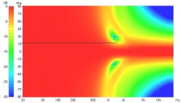
These show pretty clearly what you can expect if someone takes the time to properly design a crossover to set the nulls fairly symmetrical to the baffle normal, i.e. put the forward lobe straight out front. I will leave it to the reader to look up the measurements of popular designs to see if they meet this goal. But for the moment, we'll assume that the designer takes care to position the forward lobe reasonably well out front.
Let's look carefully at catapult's simulations.
First, the speaker with an axisymmetrical horn.
Vertical map of two-way loudspeaker having 12" woofer and 90 degree round horn, xover at 1.3kHz fourth-order

Notice the pattern collapses rapidly between 750Hz and 1kHz to approximately 30 degrees. It then opens back up above 2kHz to 90 degrees. In between, in the crossover region from 1kHz to 2kHz, you'll notice the nulls. The crossover region has basically a 30 degree vertical pattern but above and below the crossover region, the pattern is much wider, basically 180 degrees (or greater) below crossover and 90 degrees above crossover. So the vertical pattern is 180+ degrees, then 30 degrees, then 90 degrees.
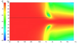
Now let's look at the speaker with an asymmetrical horn.
Vertical map of two-way loudspeaker having 12" woofer and 90 x 60 degree horn, xover at 1.3kHz fourth-order

Just like the example above, the pattern collapses rapidly between 750Hz and 1kHz. You'll also notice that the nulls are positioned at the same place as the earlier simulation - 30 degrees - which indicates that catapult's model did not take advantage of the smaller mouth height and move the tweeter closer to the woofer. He did not decrease CTC spacing in his simulation, which would have increased the size of the forward lobe and set the nulls out further apart. We know the null angle can be increased (fairly significantly) to nearly double this by decreasing CTC spacing because I've shown measurements that prove that fact. Still, the existing model illustrates the issues very clearly. The pattern narrows from 180+ degrees at LF to 30 degrees at crossover to 60 degrees at HF.
If the CTC spacing were made smaller, then the nulls would be spread out to the edge of the pattern, placing them at 60 degrees, just like the vertical pattern at VHF. What you have then is 180+ degrees below crossover, collapsing to 60 degrees in the crossover region and maintained through the tweeter's passband.
This is the goal.
These show pretty clearly what you can expect if someone takes the time to properly design a crossover to set the nulls fairly symmetrical to the baffle normal, i.e. put the forward lobe straight out front. I will leave it to the reader to look up the measurements of popular designs to see if they meet this goal. But for the moment, we'll assume that the designer takes care to position the forward lobe reasonably well out front.
Let's look carefully at catapult's simulations.
First, the speaker with an axisymmetrical horn.
Vertical map of two-way loudspeaker having 12" woofer and 90 degree round horn, xover at 1.3kHz fourth-order
Notice the pattern collapses rapidly between 750Hz and 1kHz to approximately 30 degrees. It then opens back up above 2kHz to 90 degrees. In between, in the crossover region from 1kHz to 2kHz, you'll notice the nulls. The crossover region has basically a 30 degree vertical pattern but above and below the crossover region, the pattern is much wider, basically 180 degrees (or greater) below crossover and 90 degrees above crossover. So the vertical pattern is 180+ degrees, then 30 degrees, then 90 degrees.
Now let's look at the speaker with an asymmetrical horn.
Vertical map of two-way loudspeaker having 12" woofer and 90 x 60 degree horn, xover at 1.3kHz fourth-order
Just like the example above, the pattern collapses rapidly between 750Hz and 1kHz. You'll also notice that the nulls are positioned at the same place as the earlier simulation - 30 degrees - which indicates that catapult's model did not take advantage of the smaller mouth height and move the tweeter closer to the woofer. He did not decrease CTC spacing in his simulation, which would have increased the size of the forward lobe and set the nulls out further apart. We know the null angle can be increased (fairly significantly) to nearly double this by decreasing CTC spacing because I've shown measurements that prove that fact. Still, the existing model illustrates the issues very clearly. The pattern narrows from 180+ degrees at LF to 30 degrees at crossover to 60 degrees at HF.
If the CTC spacing were made smaller, then the nulls would be spread out to the edge of the pattern, placing them at 60 degrees, just like the vertical pattern at VHF. What you have then is 180+ degrees below crossover, collapsing to 60 degrees in the crossover region and maintained through the tweeter's passband.
This is the goal.
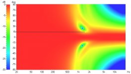
He did not decrease CTC spacing in his simulation, which would have increased the size of the forward lobe and set the nulls out further apart.
That was on purpose. Both horns had the same vertical dimension to get the cutoff low enough for the 1300 XO. Making the 90x60 smaller would have meant moving the XO higher and defeated the purpose. Here's the same 90x60 with a 15" woofer so the C-C spacing is bigger. It does make the lobe a tiny bit smaller but, like I said in the original post, these things are a continuum. Basically the vertical polar response of all of them sucks and, to me, that's a small fish in a big design pond. It's something to pay attention to but not something to obsess about. As long as the sound doesn't change when you stand up, that's good enough for me.
Edit: all the sims are using the 10" vertical dimension of the QSC 90x60. You could cut into the mounting flange and maybe overlap the woofer and horn by an inch but the sims show there's not really enough difference in the polars to make it worth the trouble.
Attachments
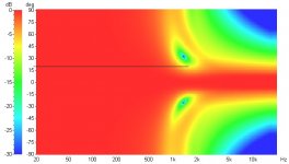
I guess I might as well post all of them. Here's a 10" woofer with the same QSC 90x60 and the same XO. Yes the lobe gets bigger but it's (IMO) a small difference.
There are a few design tradeoffs going on and the designer needs to decide what's important.
1. The 15" has a smaller usable lobe than the 10" because of C-C spacing.
2. The 15" will have more sensitivity and more LF capability than the 10".
3. The QSC has a generous roundover at the mouth. That increases C-C spacing but it should also help reduce horn honk.
The way I see it, no matter how you juggle the C-C thing, you'd like both the seated and standing ear level to be within +/- 10 degrees of the center of the lobe for the best sound. So steering the lobe is the most important thing and that is done with the crossover. The crossover is a big deal, C-C spacing less so.
Attachments
I agree with you about steering the lobe. Some guys seem to not pay attention to that and produce speakers with a null way too close to the baffle normal. Makes them hard to place without putting people in a null. Most people won't even consider that, and instead assume the baffle normal is the certer of the forward lobe. They can easily make the accident of placing the speakers where people are sitting in a null. Using careful crossover design, this can be avoided. To me, that's a requirement of good loudspeaker design.
- Status
- Not open for further replies.
- Home
- Loudspeakers
- Multi-Way
- Horn vs. Waveguide