Two impedance peaks is common for a compression driver.ZilchLab said:I confirm Augerpro's impedance measurements for DE250 on XT1086. As we see, however, a peak in the region of 1.6 kHz is common with virtually any waveguide, as is also the case with the exponential horn in the DE250 data sheet.
I've measured dozens of horns and find there are usually two easily identified electrical impedance peaks or more. Sometimes only one is large, other times two are and sometimes even more.
There's the mechanical resonance of the driver, of course loaded by the rear chamber, front chamber and the horn. These set the mechanico-acoustic resonant frequency of the diaphragm. Then there are also pipe modes of the horn, sometimes only one is there, sometimes there are one or two others, usually higher in frequency and lower in amplitude. Above that, you can sometimes see little impedance blips, caused by discontinuities in the flare or by diaphragm breakup.
All this on top of voice coil resistance and inductance. The horn loading increases acoustic resistance but it also causes reactance (and in varying amounts, rippling) which results in all those impedance fluxuations.
Re: Horn vs waveguide
Yes, but they are typically of smaller dimension, as are the drivers used with them, which may sometimes be dome tweeters:
http://www.diyaudio.com/forums/showthread.php?postid=1844489#post1844489
dobias said:Is a waveguide suitable for a 5 to 7 kHz crossover?
Yes, but they are typically of smaller dimension, as are the drivers used with them, which may sometimes be dome tweeters:
http://www.diyaudio.com/forums/showthread.php?postid=1844489#post1844489
I have not mesured as many as Wayne has, but what I've seen agrees completely with what he says above.
ZilchLab said:So much for the 1.6 kHz issue:
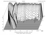
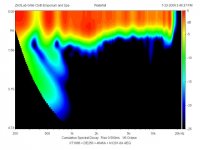
Strange. In the color 2D waterfall there seems to be a real hotspot at ~1.6K. In the 3D graph it looks lower in freq. and amplitude. Am I reading that right?
I think the values of R1/R2 in the network I designed can probably be set to provide the correct amount of damping to remove that peak. That's one of the things that network is designed to do, and why I came up with that circuit topology.
Since R1/R2 sets the damping of the core splitter filter, you can set whatever amount of peaking you want. It can be set for slightly ovberdamped or slightly underdamped, whatever is needed. That was always the whole intent of the R1/R2 network - to provide these three things: 1. SPL matching between woofer and tweeter, 2. Top octave conjugate compensation for mass rolloff and 3. Specific damping for the core splitter to set the response in the region below mass rolloff, basically the octave between crossover and mass rolloff. Usually, the circuit is slightly underdamped, but if there is a pipe mode and/or diaphragm resonance in this region then it may need to be set for other damping values. I think that's what you're seeing here, and overdamping is probably the best bet.
On the other hand, Zilch has a really nice response curve so I'm thinking whatever he did, it works well. Seems like I saw he wrote it was a notch filter. Looks like he dialed in just right, with the right L, C and R. I'm sure you could set the values of R1 and R2 to do the same thing, simultaneously setting the three conditions it's designed to set. But if the high-pass filter isn't set for around 1.6kHz, it won't do it.
It looks to me like with a little effort, this combination could be really good. Nice flat response and large forward lobe with widely spaced nulls. I'm still thinking they can probably even be coaxed just outside the 60 degree vertical pattern, but even if not, being just under at 50 degrees is very good. That's the kind of separation between nulls I like to see.
following a recommendation from Dr Earl Geddes Iv'e been using a resistor in parallel with the compression driver to even out some of the impedance issues, usually I chose a value that is the same as the impedance of the compression driver then I drop that into a lpad calculator to get R2. This knocks a few db off the sensitivity of the driver that makes it a lot easier to match levels using a active crossover and a DSP for EQ'ing. It also takes out a lot of hiss at low volume levels.
col.
col.
with the abundance of cheap, good quality class-d amplification and DSP/DAC signal processing technology I see passive crossover networks and all the work that goes into them as being a bit outdated. However, there is a lot to be learned from them. I don't propose not using any passive components but I think a combination of the two can give exemplary results.
I'm currently running a bi-amped pair of mains using two Tripath based amps that are running off of laptop power supplies. These are crossed using a Rod Elliot P09b active crossover and I use a behringer DEQ2496 for EQ'ing. This may be a bit beyond an average HiFi setup but if you are a diy enthusiast it's actually quite a reasonably priced system for the quality of the sound it produces.
col.
I would like to add a comment on Econowave Vs Earl Geddes OS waveguide. I actually love both of them 😉 I ran a pair of JBL 2407H on the PT waveguides and they were amazing, highly recomended. However, around a year ago I thought I would have a go at creating a cheap pair of Dr Earl Geddes type waveguides (cousin of Nathan). I'm not sure how worthy they are of comparison being 70 degree instead of 90 degree (dayton 10" waveguide) etc.. but using them in the active-crossover, cheap class-d amplification method i mentioned in the previous post and of course sticking a huge chunk of foam in them (courtesy of Dr Earl Geddes) they sound really, really amazing! I wouldn't go back to Econowave but I would use them in other systems.
One day when/if I have the funds I will attempt to buy some of the Dr Earl Geddes originals. Whatever you think of his designs he has dragged the whole discussion and development of horns/waveguides forward into a new era. He has to respected for that fact.
col.
One day when/if I have the funds I will attempt to buy some of the Dr Earl Geddes originals. Whatever you think of his designs he has dragged the whole discussion and development of horns/waveguides forward into a new era. He has to respected for that fact.
col.
col said:following a recommendation from Dr Earl Geddes Iv'e been using a resistor in parallel with the compression driver to even out some of the impedance issues, usually I chose a value that is the same as the impedance of the compression driver then I drop that into a lpad calculator to get R2.
That's the idea, yes. The shunt resistance provides damping and, in combination with series resistance, provides SPL level matching as well.
col said:I would like to add a comment on Econowave Vs Earl Geddes OS waveguide. I actually love both of them 😉 I ran a pair of JBL 2407H on the PT waveguides and they were amazing, highly recomended. However, around a year ago I thought I would have a go at creating a cheap pair of Dr Earl Geddes type waveguides (cousin of Nathan). I'm not sure how worthy they are of comparison being 70 degree instead of 90 degree (dayton 10" waveguide) etc.. but using them in the active-crossover, cheap class-d amplification method i mentioned in the previous post and of course sticking a huge chunk of foam in them (courtesy of Dr Earl Geddes) they sound really, really amazing! I wouldn't go back to Econowave but I would use them in other systems.
One day when/if I have the funds I will attempt to buy some of the Dr Earl Geddes originals. Whatever you think of his designs he has dragged the whole discussion and development of horns/waveguides forward into a new era. He has to respected for that fact.
I won't speak for anyone else but I will say that I think the idea of the catenary flare profile, the PS elliptical, is wonderful. It's the use of round horns and the necessity of wide C-T-C spacing that bothers me. I also don't like the tall vertical dispersion at VHF, it's just not useful even if the nulls weren't there. Those two things take the round OS horn off the table for me.
Still, the OS, PS and other similar CD horns are in the same family, I think. It's just that, to me, the whole loudspeaker system must be considered, not just the horn. When you look at the whole picture, I think it makes the elliptical and rectangular asymmetrical CD horns much better suited for home hifi. You can always use a PS horn with the foam inserted, using all these ideas in one package.
You can always use a PS horn with the foam inserted, using all these ideas in one package.
now that would be a good consolidation of ideas. I'm in 😀
col
panomaniac said:
Strange. In the color 2D waterfall there seems to be a real hotspot at ~1.6K. In the 3D graph it looks lower in freq. and amplitude. Am I reading that right?
Yes, but if you look closely in the 3D version, there's a "bump" on the top of the plateau which shows as a hotspot in the spectrogram. Clearly, the issue is not entirely resolved as, while the resonance is well suppressed now, the region is still "fat." My intent was to discover if EQ alone had promise to mitigate it. Answer: "Yes," but there's more to do.
Wayne Parham said:I think the values of R1/R2 in the network I designed can probably be set to provide the correct amount of damping to remove that peak. That's one of the things that network is designed to do, and why I came up with that circuit topology.
It looks to me like with a little effort, this combination could be really good. Nice flat response and large forward lobe with widely spaced nulls. I'm still thinking they can probably even be coaxed just outside the 60 degree vertical pattern, but even if not, being just under at 50 degrees is very good. That's the kind of separation between nulls I like to see.
I'll migrate to your filter, most likely. What I have presently is a proof of principle kludge. The ancient relic Altec Model 19 crossovers are merely what I use for initial testing of various combinations, because they have the facility to dial in varying levels of HF comp. My own version of that has even greater versatility, but it is otherwise occupied presently.
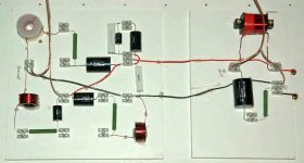
We got our first look at the Geddes crossover in member DougSmith's Abbeys recently, below. It incorporates three notch filters to smooth the DE250 response. To achieve the result I show, I did the same using DEQ2496, much as Col has just suggested. None of them is more than 2.5 dB deep, as I recall, and could be implemented passively using series LRC notches in a final design, if required....
Attachments
Hey Zilch - can you shoot me an email? I have a couple of Econowave questions that would be OT here. Thanks!
On-topic Footnote:
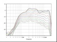
Some pages back, in discussing his "critique" of the EconoWaveguide, Earl conceded that neither it's response nor constant directivity capabilities were a problem, rather, merely that the ripples in its response were indicative of the presence of HOMs. Augerpro's recent measurement of the Geddes waveguide shows ripples as well, and, indeed, looking back at Earl's original published data, subject of this thread, his unequalized ESP12, even 1/3 octave smoothed, prominently exhibits them, below.
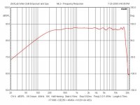
In the final comparison of ESP12 and EconoWave, however, it's apparent that his DE250 had been tamed with EQ, much as I have done with it on XT1086 here....
Some pages back, in discussing his "critique" of the EconoWaveguide, Earl conceded that neither it's response nor constant directivity capabilities were a problem, rather, merely that the ripples in its response were indicative of the presence of HOMs. Augerpro's recent measurement of the Geddes waveguide shows ripples as well, and, indeed, looking back at Earl's original published data, subject of this thread, his unequalized ESP12, even 1/3 octave smoothed, prominently exhibits them, below.
In the final comparison of ESP12 and EconoWave, however, it's apparent that his DE250 had been tamed with EQ, much as I have done with it on XT1086 here....
Attachments
To achieve the result I show, I did the same using DEQ2496, much as Col has just suggested.
ZilchLab, be careful with the DEQ2496 it can be quite deceptive. Don't use the analogue in/out. I'm using a poppulse USB with the XLR output into the DEQ2496 and then the digital/optical out to a outboard DAC. Behringer really skimped on the opamps in the analogue in/out.
col.
col said:
ZilchLab, be careful with the DEQ2496 it can be quite deceptive. Don't use the analogue in/out. I'm using a poppulse USB with the XLR output into the DEQ2496 and then the digital/optical out to a outboard DAC. Behringer really skimped on the opamps in the analogue in/out.
Yes, it's merely a development tool here, telling me what I need to do. I'd attend to those larger issues if I were to actually use it in a system design....
- Status
- Not open for further replies.
- Home
- Loudspeakers
- Multi-Way
- Horn vs. Waveguide