fb said:How does it sound? 😀
Am I awash in HOM? Not that I hear, particularly; I took 511A's down to set this up, so I know "horny" when I hear it.
It certainly has the "punch" everybody's been crying for.
Needs a sub, of course.
I'll put DE250 on next for the forum's edification, rather than tweak the filters just now.
[Those who have pushed the Iggy button are missing out on the fun.... 😉 ]
John from aespeakers has used the XT1086 in pro systems
Well, there you go. Shoulda known John & Co. had it goin' on! 🙂
ZilchLab said:
Am I awash in HOM? Not that I hear, particularly; ]
3 things:
1. Varying High output (..starting over 100 db).
2. CSD (..several horizontal points of axis).
3. Effectively *remove* mouth effects with good filtering.
That would tell you if you are "awash" in HOM's or not according the one "rock'n" the "iggy button". 😀
Inductor said:
Does any of you know if they ever worked out a crossover for that speaker? The crossover is the real heart of a loudspeaker like this, and will make or break it where polars are concerned.
I may drop John a line and see. I only scanned the thread but it looked like they hadn't worked through the crossover yet. Wonder if they finished it up, or if they changed gears to do something else. Looks like a good configuration to work with.
ScottG said:
3 things:
1. Varying High output (..starting over 100 db).
2. CSD (..several horizontal points of axis).
3. Effectively *remove* mouth effects with good filtering.
Why me? 😉
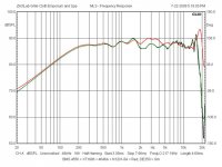
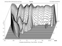
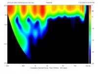
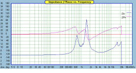
I'd expect that waveguide just sittin' there hanging out in the open by an inch or so to be ringing all over the place, but it's pretty clean above 2 kHz:
Attachments
Wayne Parham said:
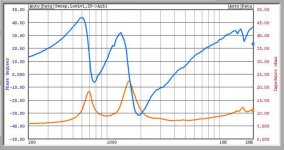
If you have time to dial in the verticals, I'd like to see what a fully optimized loudspeaker looks like, with respect to the position of the nulls, the shape of the forward lobe, you know, the polars.
The forward lobe is 48.02° wide, the upper null being at +24.44° and the lower at -23.58° from the centerline of the waveguide, with the waveguide itself ~2" in front of the baffle on which the woofer is mounted. Center-to-center distance is 10", about as close as they could be mounted. Angles were measured from the DE250 screen in the waveguide throat, 45" from the mic. The curve is still flat above the nulls at -4 db, so the nulls are occurring within the waveguide pattern control window. The nulls were located at -40 dB.
Don't know about "fully optimized," but it's no stinker, clearly, even using this vintage relic crossover. I'd say these results are very similar to those you demonstrate for 3-Pi....
That looks pretty good with respect to the vertical nulls. I wonder if you could move the crossover frequency down a smidge to increase the height of the forward lobe, putting the vertical nulls outside the pattern. One could also select crossover frequencies and slopes that allow baffle mounting of the drivers.
I find there is some wiggle room in crossover frequency with respect to horizontal pattern matching. This is because the sound sources sum off-axis just like they do on-axis. There is no path length change from movement along the horizontal, so the phase relationship betweeen them is fixed. The two sound sources blend together nicely even at fairly wide horizontal angles, so you're really just matching the falloff near the crossover region when choosing the frequency.
The nulls you find along the horizontal plane are at very wide angles, typically between 45 and 90 degrees for loudspeakers like this. Horizontal nulls are caused by a path length difference from sound arriving from opposing sides of the the woofer (diameter). The nulls from woofer diameter occur at closer and closer angles the higher in frequency you go, but they wouldn't be narrow enough to be inside the pattern until well above the crossover point. That means there are no horizontal nulls until way outside the pattern.
This fact allows some freedom in the choice of crossover frequency, about 30% or so, I've found. The horizontal pattern of the woofer and the pattern of the tweeter blend in the crossover range. It is important that they be approximately matched and that you don't go too far, but you can use this to manipulate crossover frequency and slope to set the vertical nulls where you want them to be, optimizing the pattern in both the horizontal and vertical planes.
Wayne Parham said:That looks pretty good with respect to the vertical nulls. I wonder if you could move the crossover frequency down a smidge to increase the height of the forward lobe, putting the vertical nulls outside the pattern.
I am first wondering if we're not being a bit cavalier about ignoring the manufacturer's recommended minimum crossover frequency in using DE250:
http://www.parts-express.com/pdf/294-605.pdf
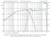
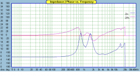
I'm going to chase that resonance at 1.5 kHz; I have verified that it is coming from the DE250/waveguide. Below's where I am now, and I'll begin by measuring the impedance and trying to notch it out.
Wayne Parham said:One could also select crossover frequencies and slopes that allow baffle mounting of the drivers.
That'll be your job; I've done the heavy lifting.... 😉
Attachments

ZilchLab said:I am first wondering if we're not being a bit cavalier about ignoring the manufacturer's recommended minimum crossover frequency in using DE250:
http://www.parts-express.com/pdf/294-605.pdf
No, I wouldn't suggest running the driver too low. When I talk about pushing the "crossover frequency down a smidge", I'm talking about manipulating the woofer's low-pass filter and possibly the tweeter's high-pass to find out if you can widen the null angles. I wouldn't suggest pushing the compression driver too low, but thinking out loud, I wondered if the crossover couldn't be optimized to widen the nulls. There are a lot of conditions to meet simultaneously, some of them with competing priority, and maximum diaphragm excursion (via crossover frequency and slope) is one of the important design criteria.
Some would probably say I've generally crossed-over relatively high, at least if you speak of the electrical high-pass filter only. Seems like everything I have works best with a compression driver high-pass of 1.6kHz.
I used to list the crossover frequency as 1.6kHz and many people over the years commented how they thought this was high. Some would comment how the driver could be run to lower frequency in home hifi use. Some would say the woofer would be in breakup. It's really hard to talk about a single number, in my opinion, because it just doesn't mean much. It's more a crossover range than a single frequency, with horn loading, diaphragm excursion rolloff slope coming into play.
I usually try to explain how the 1.6kHz figure was just a number, I'd try to explain the acoustic slope and how it combined with the electrical slope and all that kind of stuff. The truth is, if you look at just the electrical filters, the four Pi has what appears to be tweeter high-pass of 1.6kHz, 3rd-order and woofer low-pass at 1.3kHz, 3rd-order. The three Pi is 1.6kHz, 3rd-order tweeter high-pass and 900Hz, 2nd-order low-pass on the woofers. But the mechanico-acoustic properties of the midwoofers and horns/drivers add to the electrical slopes. It's all interrelated.
Still, the electrical signal sent to the compression driver (in my case) is high-passed at 1.6kHz, 3rd-order. The stop band comes on quick and excursion is limited. It's a pretty conservative alignment that offers a lot of protection for all compression drivers.
This is the general procedure I use:
panomaniac said:1.6K does not seem low to me - with a 1" driver and horn that size. Seems about right...
Yeah, I think most modern 1" exit compression drivers will handle maximum power with 1.6kHz/3rd-order to 1.2kHz/4th-order, something like that. Depending on the horn, you can use them below that but if you send 'em too much power the excursion may become excessive and the diaphragm might even strike the phase plug. That's a bad thing.
- Status
- Not open for further replies.
- Home
- Loudspeakers
- Multi-Way
- Horn vs. Waveguide