I had the opportunity to meet & speak with GM @ DIYAtlanta this past weekend. One of the things he shared regarded the response from "free" horns relative to baffle mounted horns.
GM said something like this:
A horn mouth needs to be rounded through 273 degrees in order to be fully effective. He cited Le'Cleach as an example.
My response to him was that I have been concerned for the choice between "free" or baffle mount. I told him he had just made an important contribution for the path I would choose.
I know, I know...I still regard augerpro's path as valid proof of concept...a worthy step along the way.
One of the things I will consider is the continuity of the profile. If the 90 x 40 has a tangent section for mounting on the baffle, there may be some benefit in cutting it off...losing the flat...so that the curve is continuous...and smooth.
Ed LaFontaine said:
One of the things I will consider is the continuity of the profile. If the 90 x 40 has a tangent section for mounting on the baffle, there may be some benefit in cutting it off...losing the flat...so that the curve is continuous...and smooth.
I agree and had considered that too. The QSC horn has maybe 1/2" that I would consider flat, then the baffle roundover starts. So pretty good continuity I think.
I think soongc, or maybe it was Le'Cleach showed an increasing slope of the curve sort of like a nautilus shell, was the best at smoothly minimizing the diffraction.
catapult said:Bottom line, it's the same old deal. You can nibble at the edges of pushing the nulls farther apart with the C-C spacing and the XO frequency but the real sweet spot is about +/- 10 degrees no matter what you do.
Thank you very much again for running the sims. I believe they effectively put the "asymmetrics lose pattern control below 2 kHz in the vertical" criticism to rest; the nulls assume control in the crossover region and augment the pattern, much as Wayne has taught -- these do not suck.
We determined in the earlier null sim study that EconoWave and a 10" woofer was a particularly workable combination; these results confirm that finding. A "squircle" 10" would snug it up even more.
The only criticism I have thus far is that your 90° round waveguide is only 8" diameter, and may therefore be unrealistic. A Geddes 12" waveguide, for example, would have a 12" C/C distance, not 10", and with a 15" woofer, 13.5".
Also, as is evident, moving the crossover frequency higher (to 1.6 kHz) with a shorter 6.5" horn is not so detrimental as you earlier supposed.
Now, if I may impose upon you just a bit further, we do know the specifics of the EconoWave crossover, and it would be interesting to see its impact upon your findings. It was modeled by member Infinia in another thread here:
http://www.diyaudio.com/forums/attachment.php?s=&postid=1870843&stamp=1246570511
IMO and experience regarding Geddes crossover approach... it's LPF is 2nd order electrical tuned to coincide near the midbass 35 to 45 offaxis response ie 4th order acoustical. The LPF is non textbook with an adjustable Q resistor in series with cap. This adjustable Q can be used to EQ the on-axis peak or null (with or w/o staggered xover points at the xover region). Once you become familiar with certain families of pro midbass cone materials and profiles you can dial it in pretty well. You can get up to +/-3 db of adjustment range with some networks.
The Econowave could learn to use this "Q trick" because of the wide variety of retro woofers being fitted to the JBL PT horn with their standard xover design. It would have to change a few values though.
The nice things about the Econowave xover 1) lotso baffle step compensation is pleasing compared to standard vintage wares and 2) lotso HF padding means the HP filter works and the comp. driver is well damped at all frequencies.
ZilchLab said:The only criticism I have thus far is that your 90° round waveguide is only 8" diameter
Huh, where did you get that? The sim is for a 10" waveguide and C-C spacing is set accordingly.
Now, if I may impose upon you just a bit further
Nah, sorry, I'm done. I really have very little interest in the econowave horn and I don't see myself ever using one. You can download LspCAD and do all the sims you want for yourself. 🙂
I would not suggest using a woofer smaller than 12" because the horn's horizontal directivity won't match a smaller woofer unless the crossover frequency is high. That moves the vertical nulls too close together. I suppose you could use a smaller woofer and leave the crossover frequency low to get the vertical behaviour you want, but that might result in a compromise in horizontal matching.
The sims are really useful, but now comes the tough part - Getting an electrical transfer function that augments the mechanico-acoustic slope of the drivers. The horizontal pattern is set mostly by crossover frequency, but the vertical is set mostly by phase. I've been doing this a long, long time, and this loudspeaker configuration has been one of my specialties for decades. What I find is the right components are almost never what you'd see in a textbook filter.
Regarding the concept of adjustable Q to set the amount of damping in the crossover region, I am pretty sure I was the first to use that aproach for CD compensation, certainly the first to document it and provide a procedure for finding the right network values using Spice. The R1/R2/C1 network is designed to simultaneously perform three functions: 1. Match the woofer and tweeter sensitivities, 2. Provide top octave compensation for mass rolloff and 3. Set specific damping for the core splitter filter, effectively setting the level in the range below the onset of mass rolloff.
I don't use any of the horns discussed in this thread, but I do use one that is similar. It is probably closest to the PT-F95HF. With a 15" woofer, I am able to get 50 degrees between nulls and with a 12" woofer, about 65 degrees. Now this is a maxima, so the -6dB points are narrower than that but nowhere near +/-10 degrees. It's closer to double that. You can't even see the nulls start forming until you're within 7-10 degrees or so from the maxima.
catapult said:
Huh, where did you get that? The sim is for a 10" waveguide and C-C spacing is set accordingly.
I apparently misunderstood 10" as being the C/C distance.
So, the 90° round waveguide is just a bit smaller than the 10.625" DDS Engebretson ENG 1-90 Pro. My point was that the model is not representative of the Geddes 12" axisymmetric waveguide in combination with a 12" woofer such as ESP 12 or Abbey.
catapult said:
Nah, sorry, I'm done. I really have very little interest in the econowave horn and I don't see myself ever using one. You can download LspCAD and do all the sims you want for yourself. 🙂
LR4 is the acoustic slope, no? If so, a more comprehensive model must be constructed from the unfiltered measurements and the filter schematic, and I'll have to generate the raw data....
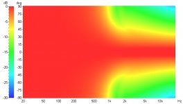
Well, I said I was done but I already had these on the hard drive. Executive version, you can make almost anything work.
Horizontal response, QSC horn, 15" woofer, LR4-1300.
Wayne Parham said:I would not suggest using a woofer smaller than 12" because the horn's horizontal directivity won't match a smaller woofer unless the crossover frequency is high.
Horizontal response, QSC horn, 15" woofer, LR4-1300.
Attachments

I would expect a 15" woofer to narrow to 90 degrees beamwidth around 1kHz, 12" woofer to narrow to 90 degrees around 1.3kHz, a 10" woofer around 1.6kHz and an 8" woofer around 2kHz. So while I think the 12" woofer is ideal for 1.3kHz crossover, I think a 10" woofer would probably work pretty well in this case too. I find about 30% wiggle room is acceptable since the two directivities blend in the horizontal plane. The sim does a pretty good job of showing that.
On the surface a higher directivity design shouldn't need much of a roundover
Hi,
I have not found this to be true. In my experience the directivity gets messed up (among other things probably) if you don't have the round over. For one example, see:
http://ldsg.snippets.org/HORNS/conical.html
Hi,
I have not found this to be true. In my experience the directivity gets messed up (among other things probably) if you don't have the round over. For one example, see:
http://ldsg.snippets.org/HORNS/conical.html
Good sims, John, very useful. You can clearly see the "squiggles" in the pattern way off-axis of the conical horn. It looks like self-interference of the edge reflection and the direct sound. Then again, it's way off-axis, back behind and beside the horn. I wonder if boundaries might improve that, like corner loading, sort of a mouth extension.
I also see the wavefront modification from the sharp edge at the entrance of the conical flare. I think this would be improved by the smooth transition of a quadratic or catenary throat (from a planar source). I don't know how much that helps, but I've always kind of thought tweeter horns with smooth features sound better, so the quadratic and catenary throat approaches seem sensible to me, at least for compression drivers.
I sometimes wonder about my choice of a cone driven conical midhorn in some of my speakers. It always seemed to me that it would be a great choice when tucked away in the corner, sort of a built-in mouth extension. After gaining measurement capability, I found that it does, in fact, measure very nicely in this configuration, both in the horizontal and the vertical. It sounds very smooth and natural to me too. But I wonder if and how much additional improvement might be realized by smoothing the throat and mouth transitions. The driver isn't a planar source, so it isn't quite the same thing and that makes me tempted to setup an FEA simulation like you have to see what the wavefront looks like coming from a cone-shaped diaphragm driving a conical horn tucked in the corner of the room.
On your webpage comparison of the LeCleach and conical horns, you commented that you thought the most important thing was smoothness of directivity transitions. I agree with you that it is more important that directivity transitions be smooth than for the tweeter horn to have constant directivity. Of course, these aren't mutually exclusive but where I would choose one over the other, I think I would choose smoothness/gentleness of directivity change and overall spectral balance.
Perfectly constant directivity would be the goal but where this is not possible, the next best thing is a smooth transition in directivity. I also think off-axis sound should be spectrally balanced, and that it should have off-axis response that sounds natural. I think that's why a DI-matched two-way can sound pretty good even though at the low end it's omnidirectional and up high it becomes directional. This isn't contant directivity, but if done right, the transitions are pretty smooth.
I'd much rather have a horn that could be implemented in a speaker in such a way that the transitions through crossover regions could be done relatively smoothly than one that had perfect CD but could not be implemented without making abrupt changes in directivity. Seems to me it's of little use to have a horn with the perfect CD pattern if it cannot be integrated into a speaker without really screwing up the pattern.
A few more comments on roundover, both cabinet edge and horn mouth:
I studied this fairly heavily in two periods, first in the early eighties as a empirical listening evaluation from a small number of music lovers. This was basically done by building two sets of loudspeakers equivalent in every way except cabinet edge rounding. The second time I studied it was related to (tweeter) horn mouth rounding and it was done purely by measurements. I have drawn conclusions from the obvervations I made in those two times in my life and rather than restate everything here, I'll link an earlier post where I described them in some detail:
I've been pondering John's sims, and thinking out loud here, I'm wondering two or three things. I wish I had time to study this with BEM, make some models like John did and look at it more that way. John - I'd love to ask you to do some more sims, and if you have time and inclination, please do. But I certainly wouldn't presume to expect that from you. I'd just like to try and model two, maybe three more things:
1. I'd like to see the effect of corner loading, essentially taking a 90 degree conical horn and putting it in a corner. In a sense, the room walls become the side walls of the horn, so the wavefront cannot travel around the side of the mouth. I'd like to see it in various positions away from the apex, from directly placed to maybe 2 wavelengths at the bottom of the passband. You can see where I'm going with that.
2. I'd also like to model the sound source as a cone rather than as a plane. It may be better or it may be worse, I don't know, but it would definitely be different.
3. With a cone source, it may not make sense to round the throat with a catenary or quadratic radius, since the source isn't planar. But then again, some entry shapes might make sense. I'd like to see what different entry shapes do. I realize that a phase plug can be developed to match cone to throat, and/but I'm wondering what are the simplest entry shapes that work well.
Again, just thinking outloud, it seems to me that the ripples that show up in the simulation way off-axis and behind the horn probably are worst outdoors, but then again, outdoors those sounds are moving away from the listeners and should be inaudible. Indoors, the walls will reflect this sound but it would seem to me that the room effect would be much greater, doing a whole lot more to the wavefront shape. It's an interesting set of effects to consider.
Last edited:
If you had perfect corner loading, no room walls besides the corner and a perfect throat, then the waves would be perfect. In a real room where you didn't have the waveguide built into the corner of the room (ie, there's a transition from the horn to the walls), then at low frequencies where the step and flair rate change is small compared to the wavelength, things would still be fine. At higher frequencies, you'd start to see the effect of the step to the wall. I personally am not going for the high frequency devices positioned in the corner of a room, so I probably won't run that specific sim. Plus the fact that I'm doing axisymmetric sims and that case would not be axisymmetric would lead to it being less useful. Doing the full 3D sim would take a lot longer.
Similarly, at low frequencies the cone source doesn't matter. When wavelengths get longer relative to the horn dimensions it does, but probably more so because of the lack of a phase plug. In the models I showed it's not specifically shown, but the diaphragm is a shallow vee shape - it's the JBL 2402 diaphragm, and the mechanical vibrations are simulated. I'm not just putting in a plane wave at the start of the horn. Anyway, I'd think the waves coming out of a smaller throat with a cone driver would be plane or something close in the frequency range where it had good performance, so that really wouldn't be a big deal. If you wanted to use it higher, make a phase plug and then you'll have plane waves at the throat again (assuming it's designed for them).
Similarly, at low frequencies the cone source doesn't matter. When wavelengths get longer relative to the horn dimensions it does, but probably more so because of the lack of a phase plug. In the models I showed it's not specifically shown, but the diaphragm is a shallow vee shape - it's the JBL 2402 diaphragm, and the mechanical vibrations are simulated. I'm not just putting in a plane wave at the start of the horn. Anyway, I'd think the waves coming out of a smaller throat with a cone driver would be plane or something close in the frequency range where it had good performance, so that really wouldn't be a big deal. If you wanted to use it higher, make a phase plug and then you'll have plane waves at the throat again (assuming it's designed for them).
Agreed. The closer the horn is to the corner, the higher frequency it will step to the wall. That's why I was thinking in terms of wavelength, relative to boundary distance. What that suggests to me is that the walls act as good mouth extensions at low frequency. The typical framed drywall home is somewhat lossy, so the walls tend to provide a little bit of damping, probably a good thing at low frequencies. Not sure how high this damping works though, it probably depends a lot on how far apart the studs are (standard 18") and how thick the drywall is. My guess is for a bass bin, the damping is probably helpful, for a midbass or midrange horn, the damping probably isn't doing as much.
You commented that the waves would be perfect if there were "no room walls besides the corner" as an open trihedral corner, and I'm assuming your inferrence is to room modes. I agree that below the Schroeder frequency, those are an issue. How much an issue depends on room damping. I have usually found that homes having rooms with framed drywall construction are much better in this respect than rooms with rigid walls like concrete, plaster or brick. Rooms with rigid walls can really be a problem, and benefit from panel absorbers. It's sort of like adding a false wall.
I started embracing Welti's multisub configurations around 2003, and I find that a similar philosophy works wonders in the lower midrange, just below the Schroeder frequency. I sort of combined what I saw in measurements of arrays (no floor bounce) with what I learned from Todd Welti's multisub studies to apply to the upper bass and lower midrange. Basically, I just overlap the mids with the woofer, positioned in different places in 3D space. When using a two-way speaker, a flanking sub can be used to the same effect.
This certainly doesn't make the wavefront "perfect", in fact, it creates dense interference between the reflected and direct modes. But I do think it sounds good and is probably the best solution for smooth sound in the modal range. Damping (drywall or panel absorbers) and multiple sound sources are both helpful in that regard.
It's a sim done in LspCAD using 'perfect' drivers and a 'perfect' crossover transfer function. The horn's directivity is simulated with a text file and the woofer's directivity is simulated with piston diameter. You could use real measurements if you had them and a real crossover if you had the schematic. You can download the demo version and it will do everything except save files and model more than 2 drivers.
I guess you could make the dB range smaller but I've wasted too much time on this already. 🙂 It's just meant as a 'this is the general idea' visualization, nothing too precise. I started doing these to answer the question 'could the QSC horn work with a 15" woofer' and I concluded that it could without any huge penalties.
I don't know about the QSC horn you're talking about, but I do think 12" and 15" midwoofers work very nicely with the right crossover to 90x40 to 90x60 horns having mouth aspect ratios that match the flare ratio, such as is the case with a prolate spheroidal horn or a radial horn, something like that. That's been my approach for years, and I've been very happy with it. I've looked at it from all angles and don't see any downsides - It's a fully optimized loudspeaker configuration, in my opinion.
About your LspCAD models, I meant to ask earlier, but the DIYaudio website was down at the time and then I forgot.
You said you used piston diameter to model the woofer's directivity, which makes sense. But what specific values did you use? I ask because I have found both by models and by measurements that woofers 10" and smaller have pretty wide patterns even up above 1kHz. I'd say 10" woofers are probably the lower limit (size-wise) for a DI-matched two-way speaker, and I really prefer larger midwoofers because of their directivity and sensitivity.
The radiating diameter of a woofer is smaller than its advertised diameter. A 15" woofer, for example, usually has something like 13.5" radiating diameter. A 12" woofer is usually around 10.75" and a 10" woofer is about 8.75". This is fairly significant, because smaller radiating diameter results in a wider pattern at higher frequency. When calculating directivity, if you enter 10" as the radiating diameter, you're really modeling a 12" woofer. If you enter 15" as the woofer's radiating diameter, you're actually calculating the directivity of an 18" woofer.
The cone shape and dust cap usually has an effect too, but the flat piston model won't include that. You could always make measurements, but even without that, I think I'd still want to plug in the radiating diameter instead of advertised diameter and I wonder if you did that or not. I would expect the LspCAD sim to be pretty close if the actual radiating diameter were entered. Then again, it's also dependent on the directivity values you entered for the horn, the positions of the drivers (vertical as well as fore-aft) and the acoustic filter slopes of the crossover, so I suppose there are a few other things that could affect the simulation too. Could be some wiggle in other areas.
Every 10" (and smaller) woofer I've measured had to be crossed over pretty high to get horizontal matching with a 90° horn. That put the vertical nulls too close together, which is why I stick with 12" and 15" woofers when combining direct radiators with horns in DI-matched two-way speakers. I mean, a slightly smaller driver is do-able, since the horizontal directivities of the two sound sources blend. Horizontal matching isn't as tough to do as getting the vertical pattern right, because there you're dealing with the path length interference nulls in addition to the directivities of the two sources. The vertical performance is an exercise in balancing competing priorities. But still, all in all, I find 12" and 15" woofers to be nicest to work with when designing DI-matched two-way speakers.
Directivity is not really the only reason, it's not the only thing I find is matched. When the midwoofer is 10dB to 12dB below the tweeter, there's just enough difference for passive EQ for power response. The larger woofers tend to provide decent extension with the right sensitivity too, and that helps match SPL as well as directivity. I suppose that moves a bit towards personal preference, but I just find 12" and 15" midwoofers tend to work better in terms of box size, extension, sensitivity and directivity.
Hey Wayne,
I used actual piston diameter, not frame diameter, for the sims. C-C spacing was set by frame diameter. I forget what numbers I used but I adjusted it so the frequency of the first null at 40 degrees off-axis matched Brandon's measurements. They all came out somewhere close to 2" smaller than frame diameter so that's probably a decent rule of thumb.
Edit:
My sims showed that directivity matching sets the upper limit of the crossover frequency, not the lower limit. There's no problem crossing lower as the combined pattern goes smoothly from 180 (or more) to 90 as the horn blends in. Crossing higher is a problem as the pattern narrows too much due to woofer directivity and then widens again as the horn comes in.Every 10" (and smaller) woofer I've measured had to be crossed over pretty high to get horizontal matching with a 90° horn.
Last edited:
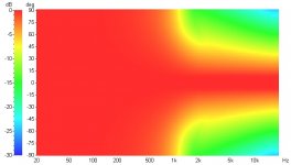
Breaking out LspCAD one more time with an exaggerated example to show there's no polar penalty for using small woofers and/or low crossover frequencies. Horizontal response with the QSC horn and an LR4-1300 crossover. The first one has an 'optimum' 12" woofer and the second one has a 1" woofer (imagining such a thing could exist). There's not enough difference to worry about.
Attachments
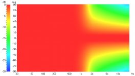
I'm skeptical because the smaller the radiator diameter and/or lower the frequency, the wider the pattern. A 1" direct radiator is nearly omnidirectional and clearly not matched with a 90° horn. I do not think that is a desirable pairing, do you? Are you advocating a position that the woofer should be arbitrarily small?
The problem I see with that approach is, at the low end, a small woofer will be omnidirectional and if small enough (like your 1" exaggerated example), it will remain nearly omnidirectional through the crossover overlap region. As it enters the stop band, its wide pattern will become attenuated and the directivity of the tweeter will become predominant. This shows pretty clearly what I was saying that the horizontal matching is more forgiving, because the two directivities blend. But this isn't matched directivity, it's blended.
If this is what you are saying, I remain skeptical. I have not found small midwoofers to match well with 90° horns. I'd like to see measurements of an actual system made this way for comparison with larger models. Sure you can do it, but I don't think it will perform as well.
- Status
- Not open for further replies.
- Home
- Loudspeakers
- Multi-Way
- Horn vs. Waveguide