No, I don't have any. Nor do I even know where to find them - other then Earl's speakers.
Would measure them if I had them.
Would measure them if I had them.
There is some poor understanding about diffraction due to the fact that this term is in wide misuse by salesmen.
Giving a closer look – for example - "diffraction horn" simply is such a misnomer – same for the claim, having a "least diffraction horn contour" invented or the like.
In the context of this thread my point regarding "diffraction" is not that important – and also it has been extensively covered in other places - but nevertheless it might be worth to recall that "diffraction" *has* to occur in order to flood all space available with sound.
Simply – we *have* to bend the "one vector wave front" released by our drivers – and we have to bend it all around (180 deg either side) no matter what contour we use for that – and "diffraction" actually is the only tool available to do so.
The point regarding horn honk now is, that we get *reflection like* behaviour at points where – due to diffraction – a so called "second source" gets created.
Obviously - *any* diffraction (=bending of the wave front) produces such a second source – so – all along *any* horn contour we get reflection.
The trick now is, to do that in a manner to get the smoothest possible results – which leads us to the need for "aligning diffraction" accordingly.
Michael
Last edited:
Giving a closer look – for example - "diffraction horn" simply is such a misnomer – same for the claim, having a "least diffraction horn contour" invented or the like.
Hello Michael
Why is it a misnomer?? Many CD horns use a difraction slot to contol the upper frequency limit of the horns directivity. The width of the slot determines what the upper frequency limit is. That's how they work.
Rob🙂
What type of foam product can be used around the mouth of the horn to also eliminate some of this honk? Maybe dense fiberglass stuff like OC703? Or think wool type products?
What type of foam product can be used around the mouth of the horn to also eliminate some of this honk? Maybe dense fiberglass stuff like OC703? Or think wool type products?
Breatheability is the primary determiner. Various products can be used with varying effect. Wool is generally considered best but tough to get thick and expensive. For foam, make sure it's open cell. You should be able to blow air through it. There will be some resistance but you won't have to 'push'.
Fiberglass works too but is hazardous. Stuff like cotton/bamboo/polyester batting works as well.
THis is for outside of the mouth and not in the mouth. Like the towel idea around a tube.
My next waveguide build will have something built into the baffle around the horn, I just do not know what yet. 1" OC703 will be fine because it will be wrapped in black fabric anyways. Similar to all my in room DIY panels.
Hello Michael
Why is it a misnomer?? Many CD horns use a difraction slot to contol the upper frequency limit of the horns directivity. The width of the slot determines what the upper frequency limit is. That's how they work.
Rob🙂
Not a bad question 🙂
Yes its "diffraction" that makes the so called "diffraction horns" work.
The misnomer lyes in that we are forced to think that any other horn contours does *not* use that mechanism of diffraction - *thats* the misnomer !
Quite any horn contour is a diffraction "generating" device so to speak - or even better put - simply - we have to be aware that diffraction *always* enters the picture.
Even more - its always the same bending (=diffraction) that is needed ! - or put it the other way around - its always the same diffraction happening anyway (Its at least 180 deg either side for 4Pi and 90 deg either side for infinite baffle application) - though not necessarily at the same points in space - which actually leaves us the (only) freedom to arrange that points in space.
Hence my statement: we can't minimize diffraction - but we can *align* diffraction...
Pretty simple - no ?
Michael
Last edited:
Hence my statement: we can't minimize diffraction - but we can *align* diffraction...
Of course you can minimize diffraction. How do you propose to "align" different diffraction points in 3 dimensional space. Their different origins makes them temporal.
Rob🙂
I have been a fly on the wall since this thread started. And if this has been covered please forgive me.
From what I have worked with and what you guys are measuringI I think this little statement might have application.
An optimally designed horn is best described as a mechanical impedance transformer. That is the impedance of the air close to the driver diaphragm and on out from it. If it truly has been designed to this narrow description it will have a limited bandwidth of usually two octaves. Over this narrow range a horn can be designed to have a minimum of irregularities that will cause gross impedance fluctuations from the air around the driver diaphragm along and out to the horn mouth. I think a couple of the horns spoken about fit this criteria and are generally considered to sound most life like. The horns with the trick contours to extend their range are the ones that generally have the greatest amount of honkiness. The round horns that are made with care and in kepping with the idea of smooth mechanical air flow seem to be the ones that sound the most life like.
But I as well as those posting am interested in the reasons why and when things start to go wrong! I'm learning new things from this thread and for that I am grateful.
Mark
The misnomer lyes in that we are forced to think that any other horn contours does *not* use that mechanism of diffraction - *thats* the misnomer !
From what I have worked with and what you guys are measuringI I think this little statement might have application.
An optimally designed horn is best described as a mechanical impedance transformer. That is the impedance of the air close to the driver diaphragm and on out from it. If it truly has been designed to this narrow description it will have a limited bandwidth of usually two octaves. Over this narrow range a horn can be designed to have a minimum of irregularities that will cause gross impedance fluctuations from the air around the driver diaphragm along and out to the horn mouth. I think a couple of the horns spoken about fit this criteria and are generally considered to sound most life like. The horns with the trick contours to extend their range are the ones that generally have the greatest amount of honkiness. The round horns that are made with care and in kepping with the idea of smooth mechanical air flow seem to be the ones that sound the most life like.
But I as well as those posting am interested in the reasons why and when things start to go wrong! I'm learning new things from this thread and for that I am grateful.
Mark
Hello Mark
Not a very useful bandwidth. Especially at 1K and above or a folded bass horn for that matter. A 2 octave horn why bother??
If you are talking about diffraction slots as trick contours I think you are missing the point. The slot or contours are not there to increase bandwidth. They are there to keep the directivity constant with frequency and extend the upper limit of the directivity.
If you mean that extending the directivity control to a higher frequency extends the useful bandwidth of the horn I can see what you are getting at.
Rob🙂
it will have a limited bandwidth of usually two octaves
Not a very useful bandwidth. Especially at 1K and above or a folded bass horn for that matter. A 2 octave horn why bother??
The horns with the trick contours to extend their range are the ones that generally have the greatest amount of honkiness.
If you are talking about diffraction slots as trick contours I think you are missing the point. The slot or contours are not there to increase bandwidth. They are there to keep the directivity constant with frequency and extend the upper limit of the directivity.
If you mean that extending the directivity control to a higher frequency extends the useful bandwidth of the horn I can see what you are getting at.
Rob🙂
I have yet to see a commercial horn that stays in phase for more than a decade. There are many horns that make noise over a wide bandwidth but not stay in phase. I can say the same about many midranges and especially tweeters. Many many tweeters stay in phase over only 2 octaves. Some of these are considered to be quite good (not by me) by those who do not care about coherence.
Can you elaborate a bit on what you mean by "stays in phase"?
Do you mean the phase does not vary more than x degrees over the bandwidth of the horn? (relative to some reference point)
Thanks!
Do you mean the phase does not vary more than x degrees over the bandwidth of the horn? (relative to some reference point)
Thanks!
I have yet to see a commercial horn that stays in phase for more than a decade.
What does in phase mean?? Without a 180 reversal??
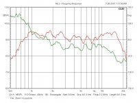
Here's a JBL 2344 it's a 1" 1K Diffraction horn used in the 4430/35 monitors that were the original CD monitors from the 80's. Doesn't look that bad to me over it's intended bandwidth especially compared to those 2 octave tweeters.
Rob🙂
Attachments
Last edited:
Not a very useful bandwidth. Especially at 1K and above or a folded bass horn for that matter. A 2 octave horn why bother??
First I'm not a designer of high frequency horns. I'm reading what you guys are writing and correlating it with what I'm finding in low frequency horns. There is a relationship.
I cannot agree more with you on this one. But consider where you start your octaves and tell me how many smaller top end horns sound bad?
From my limited experience with high frequency horns I think it's the ones that drop down into the lower midrange that can be most problematic.
As for trick horns. I mean the ones where we see a flare discontinuity that is introduced to support a greater gain in the the low end of the driver's output. That is not following a smooth curve from throat to mouth.
I'm guessing but I think it is usually done to shorten the length of the horn. Electro Voice has a few as does JBL and I have recently listened to some honki Kilipsch midrange horns. I'm sorry I don't remember the model numbers. But they do have the same common traits.
If you mean that extending the directivity control to a higher frequency extends the useful bandwidth of the horn I can see what you are getting at.
Yep that is what my meager typing is trying to get at.
Isn't the entire idea of horn loading a driver to control it's dispersion so that we trade bandwidth for SPL gain?
Well that's my little bit of wondering. I'll keep reading and learning a thing or two. You guys have me thinking about trying my hand at designing some high frequency horns now. Thanks! 🙂
Mark
Staying in phase
First some definition-
There are 3 domains- Time, Frequency, and Energy
Frequency response is simply measuring the level radiation. So long as clipping or significant power compression is not occurring this measurement will tell us only the frequency dependent efficiency of converting electrical energy into acoustic energy.
Phase or time response tells us the relationship between the time the energy is applied to the transducer and the time or phase the energy is radiated from the transducer.
Energy is the power compression or clipping characteristic of the transducer.
These three domains define the transducer pretty well. Only measuring one domain does not inform us of the useful bandwidth of the transducer. To be completely useful to the ear brain receiver the phase of the signal must stay relatively constant throughout the usable bandwidth. When the transducer looses phase (become incoherent) or changes phase the ear brain will use that information only to determine the energy level in the band and not any cues or its harmonic relationship to lower frequencies. These incoherent and out of phase signals are used only for frequency balance and not to form image or to know how a particular (say musical instrument) sounds.
All transducers exhibit phase change outside their passbands. The (hopefully) large region where the phase remains relatively constant is the passband. In this passband EQ may be applied to flatten the frequency domain. Incoherent areas cannot be equalized. Correcting a transducers phase response errors is not so easy bordering on the very very difficult to impossible.
So a good driver has a wide range where the signal output has a constant phase relationship. The horn we are using right now has a constant phase relationship from 1300-13000Hz. Yes it frequency response is much wider than this but outside these regions the sounds do not aid the ear brain in "hearing" the music or content. Indeed it makes it more difficult to hear. We have found it best to limit the signal to the coherent band for the transducer as this makes hearing the sound very easy by eliminating the "incoherent garbage" of the out of band signals. The ear brain effectively throws away incoherent signals anyway right after the energy level and incoherent aspects are determined by the ear brain.
In listening have you ever notice how a very few systems are just so easy to listen to and do not fatigue the listener? On the other hand we have all heard systems which are very tiresome to listen to even though it is difficult to say why? A highly coherent signal takes little effort for the ear brain to hear and decode into intelligible information. I highly incoherent signal takes huge efforts for the ear brain to pick out the coherent useful information and is therefore very fatiguing.
OK, cool. Do you have measurements of the Dayton horn + Eminence driver to share?
I'd like to get a look at what is working well for you, so that it can be compared to some other stuff. Thanks!
I'd like to get a look at what is working well for you, so that it can be compared to some other stuff. Thanks!
Will be retesting this exact setup very soon. May have the results from the earlier test recorded in the test system however the the test setup went to a system this very morning for setup of that existing system. Thanks for asking.
Of course you can minimize diffraction.
Don't think so – look at above...
😉
How do you propose to "align" different diffraction points in 3 dimensional space.
to “align diffraction” describes the way of “how to” - the individual gaols may be different – mine is to develop towards smooth sound field *and* preserving as much CD behaviour as possible.
Has not too much to do with the topic here, besides that this goal also may have inherent low reflection – but as long as we don't have the tools to objectively measure and compare - this is just my guess
😉
Their different origins makes them temporal.
Sure – so what ?
An optimally designed horn is best described as a mechanical impedance transformer.
Yes – this has been said for quite a while -
but others say, an optimally designed horn is best described as a directivity control device.
and others say, an optimally designed horn is best described as a device to generate some comforting tension in the spine.
and me saying, an optimally designed horn is best described as a diffraction aligned device.
And lately its even been said that an optimally designed horn is best described as a "non–honk" device – LOL !
Make your pick !
🙂
Michael
Last edited:
What is and how to measure phase.
Start with an electronic cosine wave. Now apply that cosine wave through an amplifier to a transducer. The transducer changes the electrical signal into an acoustic signal and radiates the acoustic cosine wave. Next a microphone detects the cosine wave and converts it back to an electrical signal. This signal is compared back to the original signal.
In this arrangement are many delays. If the delay is measured at the center of the bandwidth of the driver the delay time through the entire system may be determine. Of course this means the driver frequency bandwidth information has already been determined, its' band pass performance. Not the coherent bandwidth though. This delay is known as excess time.
With this delay info and control of the cosine wave a frequency by frequency measurement is made to determine the difference in phase at each of those frequency by subtracting off the excess time and then calculating the phase error at that specific frequency. Phase error in degrees is frequency period divided by the difference in time of the arrival of the cosine wave multiplied by 360.
Anyone can argue this is not a valid measurement and I do not wish to argue in favor of this method. This is one of the two ways phase is measured here. The other way is the classic two tone test where one tone is used as reference and the other is varied in frequency. These two methods have lead to surprisingly similar results so we use the easy way.
IMO, it's easy to get confused and misled by all this phase and group delay stuff. One of the things I really like about ARTA is its ability to plot excess phase and excess group delay. Definitions as I use them:
Actual phase: measured phase with the time of flight removed.
Minimum phase: phase calculated from the magnitude response with a Hilbert-Bode transform. This is the phase that an electrical filter with the same magnitude response would have. If the device under test is minimum phase, electrical EQ will fix the phase response when it fixes the magnitude response. Flat magnitude gives flat phase.
Excess phase: actual phase minus minimum phase.
Group delay: same as above except expressed in ms. rather than degrees.
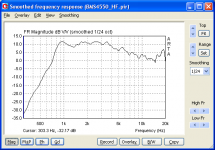
Let's look at Doug's measurement of the BMS4550 on a QSC 90x60 horn. Not sure but I think he had a large cap in series. The magnitude response tells us it isn't going to be very useful below 800 Hz.

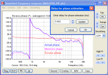
How about the phase response? The actual phase, with time of flight removed, starts looking goofy below 4K. BUT the minimum phase is almost the same as the actual phase and the excess phase is nearly flat and nearly zero. Any EQ or crossover work we do on this horn will fix the phase when it fixes the magnitude. The phase wrap around 850 isn't any different than a 4th order electrical crossover would give. The excess phase gets a little goofy above 10K but the sampling rate was only 48K so that could be an artifact of the sound card's brick-wall filter and/or the test amp's HF phase response.

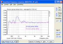
Jean-Michel likes to use group delay to choose a cutoff frequency. If you look at the actual group delay, it looks like it has big problems around 850. However, if you plot excess group delay, those go away. The group delay is strictly a function of the magnitude response, no different than an electrical filter would give. Now you might not like the sound of 4th order filters, but the sound is caused by the shape of the mag curve, not by some property of horns that is different than any other minimum phase device.

Bottom line, for this horn-driver combo, phase and group delay plots aren't giving us any useful information that isn't contained in the magnitude plot, at least as far as choosing a useful frequency range. We need to look elsewhere for distortion and that elusive horn honk.
Actual phase: measured phase with the time of flight removed.
Minimum phase: phase calculated from the magnitude response with a Hilbert-Bode transform. This is the phase that an electrical filter with the same magnitude response would have. If the device under test is minimum phase, electrical EQ will fix the phase response when it fixes the magnitude response. Flat magnitude gives flat phase.
Excess phase: actual phase minus minimum phase.
Group delay: same as above except expressed in ms. rather than degrees.
Let's look at Doug's measurement of the BMS4550 on a QSC 90x60 horn. Not sure but I think he had a large cap in series. The magnitude response tells us it isn't going to be very useful below 800 Hz.
How about the phase response? The actual phase, with time of flight removed, starts looking goofy below 4K. BUT the minimum phase is almost the same as the actual phase and the excess phase is nearly flat and nearly zero. Any EQ or crossover work we do on this horn will fix the phase when it fixes the magnitude. The phase wrap around 850 isn't any different than a 4th order electrical crossover would give. The excess phase gets a little goofy above 10K but the sampling rate was only 48K so that could be an artifact of the sound card's brick-wall filter and/or the test amp's HF phase response.
Jean-Michel likes to use group delay to choose a cutoff frequency. If you look at the actual group delay, it looks like it has big problems around 850. However, if you plot excess group delay, those go away. The group delay is strictly a function of the magnitude response, no different than an electrical filter would give. Now you might not like the sound of 4th order filters, but the sound is caused by the shape of the mag curve, not by some property of horns that is different than any other minimum phase device.
Bottom line, for this horn-driver combo, phase and group delay plots aren't giving us any useful information that isn't contained in the magnitude plot, at least as far as choosing a useful frequency range. We need to look elsewhere for distortion and that elusive horn honk.
Attachments
Last edited:
- Status
- Not open for further replies.
- Home
- Loudspeakers
- Multi-Way
- Horn Honk $$ WANTED $$