Hello Elias,
I used to listen to a quite similar horn: the Yamamura Churchill. Honkiness was not so noticeable.
We have to consider that the Kleinhorn you show (from *Pass Labs*) is a rear horn. The effect of that large horn will mostly be audible in the low frequency (bass + infra bass...).
Jean-Michel Le Cléac'h
They both also have acoustic low-pass filters via the chamber behind the driver. 😉
Nope, long story short, I moved in to take care of my elderly parents so my sound system for now is a computer and headphones. My QSC horns, along with the rest of my gear, are in storage so I'm DIYing vicariously through you guys. 🙂Catapult do you have any current builds going?
McMaster-Carr has felt. F10 and F13 are good for diffraction control.
McMaster-Carr has felt. F10 and F13 are good for diffraction control.
So polyestor type felt found on Jo-ann fabric stores isnt good for this?
Wool is better. Aside from the material, the stuff you get at the fabric store is usually too hard so it acts like a reflector at HF -- definitely not what you want in the throat. The good stuff is easy to squish between your fingers.
Question for panomaniac.
Back in post # 328, the 811_Dayton.gif seemed to me to be the best performer (if I'm reading the graphs correctly!).
Which model is that?
David
Back in post # 328, the 811_Dayton.gif seemed to me to be the best performer (if I'm reading the graphs correctly!).
Which model is that?
David
Using 3/16" thick felt ring where the hole is half the area of the throat has worked well for 1" horns. I have not done this with bigger horns.
As a note, running 10dB crest factor noise through the horn the honk really stands out as its own sound (like a train) and is easily heard. Adding this felt ring has other effects of course but a horn that honks is worthless as far as I am concerned so the overall result was good and the horn still had 1 decade of bandwidth though instead of 1400-14,000 1300-13,000 was the result. For me a small price to pay. Have not tried this on many horns, only 2 but worked both times with not hugely dis-similar results. These were screw on type 1 3/8"-18 TPI compression drivers.

I'm always a little bit astonished about that dampening methods when applied at a "discrete" place in horns – be it your application or Peavy's or similar.
Not that it necessarily might not work at all but really would like to see measurements in comparison of course...
What you actually do with dampening material is easier to get intuitively when we imagine this dampening material being way more efficient than it actually is in real world – say - for the moment - those felt, foam, cotton, wool whatever is 100% absorptive at any frequency .
It is easy to see that under this assumption you get nothing else than a "black hole" at the place the absorption material is placed.
The side effect of such a "black hole" is that where the contour ends and starts before and after that "black hole" – you have created a point of maximum diffraction with all the adverse effects of bad diffraction alignment!
Which actually is honk maximisation (!) in the context of that thread.
😉
So – even when the real world absorption material is not 100% absorptive, above mechanism happens exactly the same way – and IMO, you never have a net gain.
Things are slightly different if you place a full plug into the horn – dampening all standing waves the same (together with the original output). Actually, all that dampening measures only lead to the "black magic" of dampening a transmission *right* – something not being possible IMO – meaning - too many trade off's to accept for my taste...
🙂
Better to seek after optimisation of diffraction alignment
Just my 2ct
Michael
Last edited:
Hello Badman,
Yes I am sorry about that, my memory run out of range at the exact moment I was searching for the info...
For sure that's Pass.
I should have recall that easily as, like me, Nelson Pass uses often a series resistor in order to have the optimal damping to the loudspeaker.
(Linkwitz uses OB and I feel that they don't provide for me the kind of musical dynamics, image, etc. I am looking for...)
Best regards from Paris, France
Jean-Michel Le Cléac'h
Jean-Michel: That's from Pass Labs, not Linkwitz.
Last edited:
After all the discussion of HOMs and using a foam plug to mitigate them, look at the response curve of the newly updated Abbey 12a, with its revised crossover. Earl is using the foam to roll off the last octave much as was shown in his ALMA presentation, OR, if the foam isn't doing it, he's not doing HF comp to flatten the response:
Abbey
The curves are very different in terms of flatness of HF extension than the ESP12 presented in the "Horn vs. Waveguide" paper, as I recall.
From what I've gleaned thus far, diffraction and HOMs are VHF phenomena, above 10 kHz, whereas, "honk" is derivative of reflections a decade lower, typically, near cutoff. Different stuff.
If we want a "poster child" of honk, I nominate the JBL H91/2307 exponential. There is also a longer-throat variant, H92/2312, so the influence of length is easily investigated:
http://www.lansingheritage.org/images/jbl/catalogs/1976-pro/page18.jpg
Last edited:
Back in post # 328, the 811_Dayton.gif seemed to me to be the best performer (if I'm reading the graphs correctly!).
Hey. The file is misnamed, but it's the Altec 806A driver on the Dayton H812 1" Exponential Horn.
I chose this horn because it looked clean and simple. It is. And mounted on a baffle and/or with better termination, it ought to be even cleaner. What I don't know about is off axis response. On axis it measures well, sounds good.
I had to see them side by side...I just captured all horns with the 811.
An externally hosted image should be here but it was not working when we last tested it.
The Dayton one is the bottom right, it had no label.
What is the 811-806?
So where is the honk in those CSDs?
Is it the darkest red part showing up for more milliseconds, 811-12Inch shows that?
Somehow "how they sound" has to correlate back to these CSDs.
Remember this one..
The dark red section definitely extends out for more seconds.
Is it the darkest red part showing up for more milliseconds, 811-12Inch shows that?
Somehow "how they sound" has to correlate back to these CSDs.
Remember this one..
An externally hosted image should be here but it was not working when we last tested it.
The dark red section definitely extends out for more seconds.
I'm always a little bit astonished about that dampening methods when applied at a "discrete" place in horns – be it your application or Peavy's or similar.
Not that it necessarily might not work at all but really would like to see measurements in comparison of course...
What you actually do with dampening material is easier to get intuitively when we imagine this dampening material being way more efficient than it actually is in real world – say - for the moment - those felt, foam, cotton, wool whatever is 100% absorptive at any frequency . (snip)
😉
So – even when the real world absorption material is not 100% absorptive, above mechanism happens exactly the same way – and IMO, you never have a net gain.
Things are slightly different if you place a full plug into the horn – dampening all standing waves the same (together with the original output). Actually, all that dampening measures only lead to the "black magic" of dampening a transmission *right* – something not being possible IMO – meaning - too many trade off's to accept for my taste...
🙂
Better to seek after optimisation of diffraction alignment
Just my 2ct
Michael
The goal of the felt ring was not damping. The goal of the ring was to improve the match between the compression driver and the horn throat between two different flare rates and throat materials. The soft felt ring with hole "re-radiates" the energy into the throat of the horn at the location of the ring. With a good match there the horn behaves and honk is reduced substantially.
For Peavey horn with the foam in the mouth- those are multi-rate horns which must honk by their very nature because of the sudden change in radiation resistance at the location of the flare rate change in the throat of the horn.
Again please note honk is caused by changes in throat impedance before a good match to open air is achieved. This can be a bad match at the compression driver to throat, a step in the throat like these very stupid multi-rate horn, to small a horn mouth, or some reflecting surface located in front of the horn like a horn lens so popular at JBL. Have never identified any other source of honk in a horn with a reasonable flare coefficient. Extra short horns honk because the flare rate is wrong or the compression driver exceeds Xmax. Xmax for the compression driver just came in for the Eminence PSD:2002S-16 and is about 0.040" so over excursion of the compression driver can be a problem also.
For Peavey horn with the foam in the mouth- those are multi-rate horns which must honk by their very nature because of the sudden change in radiation resistance at the location of the flare rate change in the throat of the horn.
You sure about that?? I don't think the Quadratic Throat Waveguide is a difraction horn. Foam on the edge of horns and foan padding used inside is old hat going back to the Urei horns from 30 or more years ago.
If we want a "poster child" of honk, I nominate the JBL H91/2307 exponential.
Take a look at the measurements I posted earlier. It's obvious somethings up as soon as you run the impeadence plot. Funny how it can sound good depending on crossover points. Crossed at 500hz Yuck!!!
Rob🙂
"....
For Peavey horn with the foam in the mouth- those are multi-rate horns which must honk by their very nature because of the sudden change in radiation resistance at the location of the flare rate change in the throat of the horn.
..."
I think you are referring to the Peavy Quadratic Throat. I would not call that a multi-rate horn, and I don't know why you are speculating that it "must honk"
There is sufficient info on the quadratic throat design. Don't bother with the "white paper". There is a patent and also notes from a conference presentation (do a google search). I found it instructive to plot the flare and expansion rates and compare them against the Geddes version. They look very similar, although I won't speculate on "how close is close enough".
Also, I don't know how one can "look" at the flare and then guess at the local change in radiation resistance (or reactance etc).
811-806 is the Altec 806A driver and the Altec 811 horn. Both are '60s vintage, ot updated or rebuilt, AFAIK.
It looks like I may have misnamed a few files. I was in a hurry before leaving for a week.
They should all be named "driver-horn". So 806-811 or 806-8" round (round waveguide)
Will look back and try to straighten things out. Will also have some new measurements soon.
It looks like I may have misnamed a few files. I was in a hurry before leaving for a week.
They should all be named "driver-horn". So 806-811 or 806-8" round (round waveguide)
Will look back and try to straighten things out. Will also have some new measurements soon.
Hello doug20,
We have to be careful when analyzing multiresolutions wavelets as a wavelet having a constant number of periods of the considered frequency is used.
For a Dirac (e.g.) the (time) width at 200Hz on the wavelet graph will be 10 times larger than the width at 2000Hz and 100 times the width at 20khz.
So the spread is not important as it is very difficult to analyse it.
Now, during the analysis of wavelets graphs, spectrograms, CSD, etc. there is 2 things to consider which lead to 2 differents sources of honkiness:
1) the delay at low frequency ( = when the frequency decreases toward the acoustic cut-off frequency of the horn).
Inside the same family of horns/waveguide a horn with a lower cut-off will have a larger group delay near the acoustic cut-off frequency.
2) multiple reflections in the horn (the most important being generally due to a "mouth to throat" reflection). This leads to a "tuned pipe" sound of what I called horns having a "truncated mouth".
I'll consider for myself, that honkiness is more important at low frequency (but over 250Hz) and it is a quite audible effect. So on CSD and wavelets graph I generally choose to follow the contour of the graph corresponding to -10dB to -15dB. If that contour is smooth the honkiness is probably weak if the contour is like a saw blade then it the horn has lot of honkiness.
Additionally isolated spots inside an interval of frequency (and time) AND having a level larger than -10 to -15dB AND corresponding to an arrival time rougly equal to the double of the travelling time between throat to mouth (or between 2 sections presneting a rapid flare change) are a sign of large reflections (filtered by the horn due to the flare)
In the graph you show, -10 to -15dB corresponds to an orange color contour and is not smooth!
Best regards from Paris, France
Jean-Michel Le Cléac'h
So where is the honk in those CSDs?
Is it the darkest red part showing up for more milliseconds, 811-12Inch shows that?
Somehow "how they sound" has to correlate back to these CSDs.
Remember this one..
An externally hosted image should be here but it was not working when we last tested it.
The dark red section definitely extends out for more seconds.
Last edited:
Hello JJMIC
Thanks for your response on the set of measurements I posted. It seams that the ETC really didn't contribute that much information compared to the CSD and the rest. I thought the impedance plot was particularly noteworthy.
Rob🙂
Thanks for your response on the set of measurements I posted. It seams that the ETC really didn't contribute that much information compared to the CSD and the rest. I thought the impedance plot was particularly noteworthy.
Rob🙂
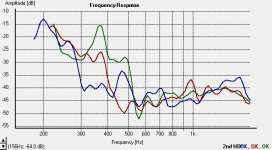
Low frequency cutoff
When I was doing the measurements of various horns, I noticed a similar rise in the 2nd harmonic at the low end of the graphs. The smaller the horn, the higher the frequency where the 2nd harmonic goes rapidly north.
So I measured and found - yep - 2nd harmonic distortion skyrockets below a wavelength that corresponds to the with of the horn mouth, flange included.
In the graph below we see only the 2nd harmonic of 3 horns with the same driver. Blue = Altec 511 Brown = Altec 811, Green = Dayton H8 horn. All driven by the same Alec 806 driver.
The graph scale is for the fundamental, so the 2nd harmonic will be an octave higher. Or you could say the distortion rises at 1/2 wavelength of the fundamental cutoff.
Nothing groundbreaking here, just fun to see it in the measurements. It's also easy to hear when doing the sweeps.
Attachments
- Status
- Not open for further replies.
- Home
- Loudspeakers
- Multi-Way
- Horn Honk $$ WANTED $$