Vielen Dank Helmut, It is nice of you.
If I well understand:
same ground point for the overall circuit:
OV= GND for : signal IN + signal OUT + power supply
Please, could you recommandate me about
power supply module and its capacitors
power transformer
I thank you really much.
Mit Freundlichen Grüssen
TYM
Hi Tym,
Im also going to build a Le Monstre, and if you allow me to give an opinion, why dont you give a try a Choke Input power supply?
Mr Eduard posted a lot of info on previous pages, and also there are a lot of interesting info about Choke Input advantages on the web.
Rgds
Nilton
Choke or Capacitor Input?
Last edited:
Hello Brazil and some others.
Thiat is one of the most informative writings by that Famous british engineer dating from 1967. Back in those days when something was printed it usually had some value!
The principles of a choke are still the same and will remain the same for ages to come.
A BIG plus from a choke input supply is that the charging pulses like you will have with a capacitor input are gone. In 1967 the general public was not using 500 VA transformer, rectifiers that could supply big current and big beer can caps. Now people will buy the biggest transformer to impress their friends, a 60A rectifier and big caps and of course a soft start circuit. Once the caps are charged they are being recharged with big current peaks because the transformer and rectifier are both capable of doing so. The transformer and rectiofier will get hotter because of this '' pulsating mode '' The wiring will radiate much more because of these pulses, the rectifiers will get more '' noisy '', the first cap will be beaten up and the rest of the supply will not be able to completely filter the nois crated in the beginning. Adding more caps ( without a CLC or CRC ) will only worsen things.
Greetings, eduard
P.s In the attachment the famous writer named cathode ray
Attachments
Hello,
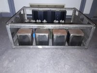
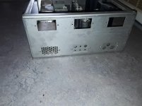
Because i was helping someone with a chassis in Italy i just positioned parts presenting the space needed in a universal mainframe ( that is the name i gave it) stainless steel chassis i made decades ago.
This is choke input supply with double rectification for each supply using a 175 VA transformer for each fase. Each channel has an independent supply but they share the same chassis.
The four rusty ( need to be sandblasted) represent the transformers.
Bourdereau choke input. First cap after that choke in between the chokes.
Closer to the circuit 2 or 4 caps for each channel.
The heatsinks are from an old Nelson pass design. They can be taken apart. Can be mounted in this area or outside the chassis.
Left and right side have 6 rectangular holes that can be closed by a perforated steel plate when not in use or used to mount a little plate with a pattern that allows binding post, rca, xlr switch, fuse holder you name.
On the inside you can install to install to L shape profile from front to back that will allow you to put two seperate( my idea) or one big ( not to smart) plate that will support everything.
Better have two separate plates so IF you need to mount something completely different you can remove one of them instead of two.
Of course a good idea to make these plate aluminium and not stainless steel unless you have very good tools!!
Greetings,Eduard
Attachments

Hello,
Because i was helping someone with a chassis in Italy i just positioned parts presenting the space needed in a universal mainframe ( that is the name i gave it) stainless steel chassis i made decades ago.
This is choke input supply with double rectification for each supply using a 175 VA transformer for each fase. Each channel has an independent supply but they share the same chassis.
The four rusty ( need to be sandblasted) represent the transformers.
Bourdereau choke input. First cap after that choke in between the chokes.
Closer to the circuit 2 or 4 caps for each channel.
The heatsinks are from an old Nelson pass design. They can be taken apart. Can be mounted in this area or outside the chassis.
Left and right side have 6 rectangular holes that can be closed by a perforated steel plate when not in use or used to mount a little plate with a pattern that allows binding post, rca, xlr switch, fuse holder you name.
On the inside you can install to install to L shape profile from front to back that will allow you to put two seperate( my idea) or one big ( not to smart) plate that will support everything.
Better have two separate plates so IF you need to mount something completely different you can remove one of them instead of two.
Of course a good idea to make these plate aluminium and not stainless steel unless you have very good tools!!
Greetings,Eduard
Hi Ed,
I like your layout demonstration since it gave us a real idea of the optimal components arrangement, keeping transformers, rectifiers, chokes and capacitors as close as possible, with short connections.
Also, it is very important to keep power supply block away from the circuit itself, and the chassi you built to me was designed according to all these premises.
Just waiting for chassis arriving here in brazil to start building my very first Le Monstre with choke input power supply! 😀😀
Rgds
Nilton
Last edited:
Hello Nilton,
The designer of the DDDAC ( also Dutch) checked the power supply of the Hiraga of my friend which uses the same LL2771 as you in a CLC configuration for his 20 watt Hiraga. LL2771 will be close or satuarate when used for a choke input Hiraga which takes 1A each channel not 650...750 mA like a Le Monstre.
For a choke input with the LL2771 you will have to use two separate power supplies. Using your transformers and 4 ll2771 will give 30 kilogrammes of iron if you will put them in one chassis. A sturdy chassis like mine in the photo will be around 5 kilo without front, back, bottom and top plate. 2....4 kilo heatsinks 3 kilo caps so close to 50 kilo.
So without any choke just the caps suppression of 100 hertz/cps - 70db with CLC identical caps and LL2771 after the first cap -115 db
Greetings, Eduard
P.s the chassis i send you on 29 september arrived at Brazilian customs yesterday!!!! Probably crossed the ocean by cano
Catastrophy!
Hi all, I have an old model Le Monstre (oh yes, original transistors) that is about to receive some descent power supply (it was a total mess (not me, I bought it second hand)) and I have planned everything so well now since a couple of years and now it was time to put things together.
AAAGGHHH! The NEC 0.47 F Supercapas that I bought some three years ago are rated 10 V, I bought them in belief that they were rated 16 V and no, I didn't check them properly when they arrived, mea culpa!! I will have around 13.2 Volts when ready so that is a big no no, not with 0.47 F!
I have 900 000 uF + 120 000 uF as is but I had planned to have appr. 2.3 F so what do I do??
Do I stay with just above 1 F or??
If someone is sitting with old NEC:s that are 0.47-0.5 F and 16 Volts, you have a customer waiting.
My problem is that I only have 130 mm hight inside my chassie but that is not enough for either Electrolytic caps around 500 000uF or Supercapas at around 500 000 uF.
Is it possible to buy electrolytic caps and lay them down or that is not recomendable??
If I now have to go either with Electrolytic caps or Supercapas to reach 2 x 0,5 F which way should I go (soundwise), please, some advise and if you have capacitors that I am looking for, another big please.....!
No need to use the old NEC's. The new NEC's are fine ... just half the capacitance and put 2 in series to handle the supply voltage.
Half??
"No need to use the old NEC's. The new NEC's are fine ... just half the capacitance and put 2 in series to handle the supply voltage."
Don't you mean double the value??
On the other hand, then I can use two of my NECs cause they will be in series..... I think. Using the second schedule!
The Monster Amp
Last edited:
Yes, two FS1A105ZF in series on each rail will give you 0.5F and 22V rating. Make sure to use the exact same capacitors to ensure the voltage splits evenly.
Hello,
Why not use this one? You just need one pair.
Greetings, eduard
https://nl.mouser.com/ProductDetail/Coiltronics-Eaton/XTM-18R0626-R?qs=BJlw7L4Cy79Jn%2BcyMqjlXg==
Why not use this one? You just need one pair.
Greetings, eduard
https://nl.mouser.com/ProductDetail/Coiltronics-Eaton/XTM-18R0626-R?qs=BJlw7L4Cy79Jn%2BcyMqjlXg==
Hmmm ... this would be an interesting solution! It can definitely handle the current and voltage. Might be a better realization of what Hiraga had in mind when he created his battery bank but technology was not ready at that time.
Hi Ed,
Hope it has space to storage some snacks too... lol...
Le Monstre PCBs arrived yesterday. The 2 PCBs with components weigh aprox. 1/2 lb and choke input must weigh 17 kilo. Lets see what choke input power supply can do for these little babies...
Rgds
Nilton


Hope it has space to storage some snacks too... lol...
Le Monstre PCBs arrived yesterday. The 2 PCBs with components weigh aprox. 1/2 lb and choke input must weigh 17 kilo. Lets see what choke input power supply can do for these little babies...
Rgds
Nilton
Back to the discussion on supercapacitors. Hiraga originally designed this amplifier and to be honest, there is nothing special about the amplifier design itself. It is quite spartan and simple. Likewise the components are nothing extraordinary. The magic lies in his power supply design. He even states in the article that the amp sounds better on battery vs the AC-DC supply.
When the amp was designed, the best he could find was the NEC supercapacitor he describes as 0.5F 10V. The closest thing I could find was NEC sold an FA series with a 10V 0.47F rating. Hiraga even admits it ran over voltage which is not a wise thing to do as the capacitor may explode. The interesting fact is the NEC is only rated at delivering 1.41mA and an ESR of 4 ohms. The cap would not be contributing much to drive the circuit.
With the technology available today, the AVX SCM series seems much more practical. I am looking to do a build and have sourced all of my components and am choosing the 1F 8.1V SCM but with 2 in series. This drops the net capacitance to 0.5F but doubles the voltage rating to 16.2V. I always run my capacitors at 80% voltage as a safety margin (bad conservative habit I learned working in the automotive industry too long 😛). The beauty is these have a current rating of 2.2A and an ESR of 0.35 ohms. This will definitely supply current to the board!
Once I get everything mocked up, I'll share some pictures but so far the plan is:
This pretty much exactly mimics Hiraga's initial vision besides the better supercapacitors. I also plan to later add the battery provisions using a set of mobile wheelchair batteries which are rated at 45Ah at 12V.
While I believe a CLC approach is better, I think we now are straying away from the amplifier as realized by Hiraga. The amplifier was designed to run off of battery and CLC will never compete with that.
When the amp was designed, the best he could find was the NEC supercapacitor he describes as 0.5F 10V. The closest thing I could find was NEC sold an FA series with a 10V 0.47F rating. Hiraga even admits it ran over voltage which is not a wise thing to do as the capacitor may explode. The interesting fact is the NEC is only rated at delivering 1.41mA and an ESR of 4 ohms. The cap would not be contributing much to drive the circuit.
With the technology available today, the AVX SCM series seems much more practical. I am looking to do a build and have sourced all of my components and am choosing the 1F 8.1V SCM but with 2 in series. This drops the net capacitance to 0.5F but doubles the voltage rating to 16.2V. I always run my capacitors at 80% voltage as a safety margin (bad conservative habit I learned working in the automotive industry too long 😛). The beauty is these have a current rating of 2.2A and an ESR of 0.35 ohms. This will definitely supply current to the board!
Once I get everything mocked up, I'll share some pictures but so far the plan is:
- Jims Audio Kit
- Antek AS-2215
- 10A Bridge
- 20 Chemi-Con 68000uF 35V electrolytics
- 8 ohm 10W dropping resistor
- 2x 1F 8.1V AVX SCM in series (replacing NEC 0.5F)
- 2.2uF 63V PPS film
This pretty much exactly mimics Hiraga's initial vision besides the better supercapacitors. I also plan to later add the battery provisions using a set of mobile wheelchair batteries which are rated at 45Ah at 12V.
While I believe a CLC approach is better, I think we now are straying away from the amplifier as realized by Hiraga. The amplifier was designed to run off of battery and CLC will never compete with that.
The supercap is an extremely poor quality capacitor. I would not use it in an audio amplifier, not voluntarily anyway.
Hello Craig,
The supercaps are nice but from what i read in the original French publications is that it all comes down to a certain mix of parts. Modern supercaps improved a lot but back then Hiraga wrote that they can NOT replace the good old electrolytic caps.
In other designs Hiraga surely used clc supplies. I have used them too. I have used CLRC and i have used big batteries as you can see in the attachments. These were used for a single rail power supply and worked well. But with a symmetrical supply like the Hiraga you will need identical voltages for both sides of the supply and that can be difficult as someone else stated here.
Busy with home improvement..Greetings,Eduard
Attachments


- Home
- Amplifiers
- Solid State
- Hiraga "Le Monstre"