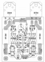
audiomanics said:My PCB layout. Single sided, short powerlines, thermal coupled transistors, Faston connectors.
Comments please.
Kees
audiomanics said:For the Fet's (2SK170 and 2SJ74):
These are grouped for their Idss: Without: 2,6-20mA
GR = 2,6 - 6,5 mA BL=6,0-12mA and V=10-20mA
Y is probably the same as V
For the normal transistors (2SC1775 and 2SA782):
These are grouped for their hfe: no ext.: 400-1200
E = 400-800 and F= 600-1200
As you have to match the transistors you have to measure the parameters of each transistor individual anyway..
For the fets you can change the resistance of the trimmer to get the correct bias and the current through the endstage.
It has been described somewhere in this tread before..
Kees
Would you be kind enough to offer a kit with the matched transistors (we can get our own resistors and caps) ?
I for one will be interested in 2 stereo pairs of amplifier to power midrange and tweeter.
Will said:
Would you be kind enough to offer a kit with the matched transistors (we can get our own resistors and caps) ?
I for one will be interested in 2 stereo pairs of amplifier to power midrange and tweeter.
Yes, i will be kind enough but unable, at least for another couple of months. Maybe, in the second halve of this year..
Kees
Maybe this will help
http://www.diyaudio.com/forums/showthread.php?postid=437769#post437769
Also; there's a thread in the tubes section that deals with CC vs tantalum
http://www.diyaudio.com/forums/showthread.php?s=&threadid=138486
Cheers,
Johan
PS I prefer tantalum (so did Hiraga)
http://www.diyaudio.com/forums/showthread.php?postid=437769#post437769
Also; there's a thread in the tubes section that deals with CC vs tantalum
http://www.diyaudio.com/forums/showthread.php?s=&threadid=138486
Cheers,
Johan
PS I prefer tantalum (so did Hiraga)
Are there any boards available for this amp besides those
from PC Design. I woundn't feal right about buying from them
with there whole line of Pass boards that are not okayed by
Pass.
On another note has anyone used those big 1F or larger
caps intended for car audio with this amp?
from PC Design. I woundn't feal right about buying from them
with there whole line of Pass boards that are not okayed by
Pass.
On another note has anyone used those big 1F or larger
caps intended for car audio with this amp?
woody said:Are there any boards available for this amp besides those
from PC Design. I woundn't feal right about buying from them
with there whole line of Pass boards that are not okayed by
Pass.
On another note has anyone used those big 1F or larger
caps intended for car audio with this amp?
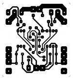
There is a board components layout from a member here. I spent two hours of image editing to make it a clear board free from components (silly a bit, as I could have made one of my own at this time 😛), so here they are. Note, I havent checked the layout for errors but it seems simple to check.
Attachments
You could also have asked Audiomanics if he wanted to post it..
Sure he would..
I will make an PDF today and post it.. Then it should be accurate in size aswell.
BTW the layout is in mirror.. that's good while transparents should be printed that way..
This print has never been made before, while i'm not able to do that at the moment. So it is never been checked working..
I think it's ok, but if you see an error PLEASE let me know..
Kees
Oh, apologise.
Do you want me to remove the attachment and having you to post your pdf?
With a quick look I did not find any mistakes, but I will have a closer look within weekend so I will let you know if I find any error. 😀
I am building my monstre using your board, so I will definitely check this.
Since this is not a conventional amplifier I am discussing some very nice ideas about the cabling for it at http://www.diyaudio.com/forums/showthread.php?s=&postid=1752007#post1752007
I find this topic interesting for ANY amplifier connections.
neazoi said:Oh, apologise.
Do you want me to remove the attachment and having you to post your pdf?
No need for apologises but it could have saved you a few hours work, as i had this in my computer already.
Goodluck making the board and testing it.. If it works fine, i'm interested in at least two of those PCB's... so..
Kees
No problem I can make these for you, but first I have to ensure they have no errors, I´ll let you know.
I have found some tantalum 0.5W resistors from china which cost about 4.50$ each and I was wondering if someone knows if there is a specific brand known for its good sounding properties or if these properties exist in all tantalum resistors.
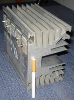
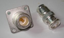
By the way, I attach the photos of some components for this amplifier to take ideas for your construction. Somehow I cannot attach them all in one post so I attach them in the next three posts.
I have found some tantalum 0.5W resistors from china which cost about 4.50$ each and I was wondering if someone knows if there is a specific brand known for its good sounding properties or if these properties exist in all tantalum resistors.
By the way, I attach the photos of some components for this amplifier to take ideas for your construction. Somehow I cannot attach them all in one post so I attach them in the next three posts.
And guess what these are. Yes these will be used for line and speaker. The most important thing is the teflon dielectric and most important the earth-first connection. Combined with the low capacitance aircom plus RF cable they should give a better performance for a fraction of cost of the super high quality junk cables sold extensively. Do not even think these things cost too much.
RF is sometimes better for audio 😀
RF is sometimes better for audio 😀
Attachments
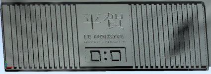
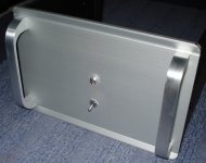
neazoi said:The front panel. Simple thick aluminum with aluminum holders taken out of an old proliant server and military surplus switch
Odos Solomou 39 ? 😉
Best electronic shop in Athens

- Home
- Amplifiers
- Solid State
- Hiraga "Le Monstre"