i have 0volts offset by using perfectly matched first stage trannies and a good quality and stable 500r trimpot. All resistors 2 watts also
hiraga
Hello,
I never did have serious problems with my hiraga build with components supplied by the people who were close to Mr Hiraga. I mean the french shop long time closed.
They used cosmos pots and shinkoh resistors. BUT if you try to copy the circuit and start using different parts everywhere. YES, you could end up with something that doesnt measure and sound properly.
Greetings, Edward
I fired up one channel and i've got on the output approx -1.5v ...
I tried to adjust but it doesnt go lower than -1.1v.
In the above picture are the actual measurements.
If i have 0.77 v across the output resistors means that i have 2.3A Bias??!!
Am i correct to adjust first the dc offset and then the bias or cand i lower the bias now?
I specified the transistors that i used in the picture.
Please help.
Cheers
Sergiu
You have quite a big difference in DC voltage across the 1k5 resistors for each polarity ( > 140 mv on about 1v). Since you have not used the original transistors the value of 180 and 240 ohms resistors may need to be re-adjusted....for my part I had to do it on my version....
Of course you still need to have a wider range of Dc offset adjustment with the pot.
For reference, I have not used the original transistors either and was able to adjust Dc offset close to 0vdc being able to go both positive and negative with the pot...
Fab
Last edited:
Ok, now i managed to set the offset to 2mv and it is varying from 2 to 10 mV and doesnt go higher. I switced from 100 ohm trimpot+2x220r resistors to a 470ohm multiturn linear 10% russian type +2x 10r resistors and the offset is rock solid.
Now i have a problem with the bias. A big problem.
The buffer and input tranies has the same beta npn and pnp of about 592.
With the 33k resistor i have a bias of 0,824v!!!...
Now i'll put in series with the 33k resistor a 10k pot.
I'll tell wats the result in a few moments.
Now i have a problem with the bias. A big problem.
The buffer and input tranies has the same beta npn and pnp of about 592.
With the 33k resistor i have a bias of 0,824v!!!...
Now i'll put in series with the 33k resistor a 10k pot.
I'll tell wats the result in a few moments.
You have to adjust the bias with the "33k" resistors value (or the 1.5k if you prefer) and then adjust 180 and 240 ohms resistors to have equal voltage for both polarities across the 1.5k resistors. Afterwards, you can adjust your Dc offset with the pot.
Increasing the 33k value is a way to reduce your bias.
Fab
Increasing the 33k value is a way to reduce your bias.
Fab
You have to adjust the bias with the "33k" resistors value (or the 1.5k if you prefer) and then adjust 180 and 240 ohms resistors to have equal voltage for both polarities across the 1.5k resistors. Afterwards, you can adjust your Dc offset with the pot.
Increasing the 33k value is a way to reduce your bias.
Fab
I'm back. I increased the values first with a 10k trimpot. With the trimpot at max (total of 43k) the voltage across 0.33 ohm is 0.78v...
I further increase this value with another 10k 1% 0.5w resistor giving a total of 53k but the voltage across 0.33 is lowered at only 0.72v!! 🙁((
This is shocking and revolting at the same time.... 😡
I measured the 0.6v across the drivers and i'm getting now 0.612 on the poz side and 0.605 on the neg side..
Instead i'm getting across the 1k5 a voltage of 0,718v that means 0,47mA to the buffer transistor wich means that i increased too much the 33k resistor.
I talked to BuffForb and he told me to lower back to 33k and decrease to 1k the 1k5 resistor wich i will do on monday, now i'm really tired....
Can someone tell me other solutions to test on monday?
Did i matched higher beta tranies than its needed for the input (mine are 595 +-2)?
Can anybody help here please?
Last edited:
I have used about 680 ohms resistors instead of 1.5k. Then, I had to use 18k resistors instead of 33k and then 165 for 180 and then 220 for 240 and it worked perfectly for 4 channels. I have used 2,2k instead of 1,8k for base output transistors and 0.33 ohms as output emitter resistors. However, you may have to play with different values since this design is very sensible to parts values and characteristics thus matching of parts is not sufficent....
You are on the good path....
Good luck
Fab
You are on the good path....
Good luck
Fab
Hi Sergiu,
Try 1.1K and 33K. That's my setup on the 30 Watt version and that works well. Do NOT put a pot in with those. They will drift too much in my opinion. Just good quality resistors 1 or 2 watt's. I use Kiwame's because of their excellent thermal properties and high precision. Afterwords you can calculate the desired values exactly as you wish the bias to be.
Measure the voltage over the bypass wirewounds and give us that number ok? If that is off, there is a different issue....... First things first 🙂 720MV across the 0.33R wirewound resistors is not that bad......
Cheers.
I have used about 680 ohms resistors instead of 1.5k. Then, I had to use 18k resistors instead of 33k and then 165 for 180 and then 220 for 240 and it worked perfectly for 4 channels. I have used 2,2k instead of 1,8k for base output transistors and 0.33 ohms as output emitter resistors. However, you may have to play with different values since this design is very sensible to parts values and characteristics thus matching of parts is not sufficent....
You are on the good path....
Good luck
Fab
Did you use lower beta tranies than mine.
I found that the philips/nxp trannies are the closest thing to the originalls 2sa/2sc or ksa/ksc input and buffer.
What trannies did you use and how high is the beta?
I think i have to do the opossite of what you did :
1) go to 43k with the 33k one (one10k in series addenum);
2) go to 1k trimpot and lower to 600-750 with the 1k5 one;
3) 1k8+ 500 ohm trimpot for the 1k8 and adjust to 2k2;
What do you say?
Thanks in advance
Cheers
Sergiu
1) and 2) are to be adjusted accordingly whatever you choose. It is sadly a trial and error process since the values are also dependent of the vbe of transistors. The HFE only influences the 4 input trannies.Did you use lower beta tranies than mine.
I found that the philips/nxp trannies are the closest thing to the originalls 2sa/2sc or ksa/ksc input and buffer.
What trannies did you use and how high is the beta?
I think i have to do the opossite of what you did :
1) go to 43k with the 33k one (one10k in series addenum);
2) go to 1k trimpot and lower to 600-750 with the 1k5 one;
3) 1k8+ 500 ohm trimpot for the 1k8 and adjust to 2k2;
What do you say?
Thanks in advance
Cheers
Sergiu
I have used 2sc2240 and 2sa970 with high HFE but do not remember the values.... This has an effect on the "33k" value and base resistor 180 and 240.
The pot should only be used for finding the right value but I prefer temporary soldered parallel resistors over the original ones to lower value....
Lowering the 1k resistor reduces your bias and lowering the 33k resistor increases the bias. You have to find the right combination to have about 1ma bias across the "1.5k" resistor location.
3) do not change your value or use pot. Just play with 33k and 1.5k.
Just to be on the safe side, start with lowering the 1.5k resistor to have a lower bias than desired and then afterwards reduces the 33k resistor which will increase the bias to,proper value. Or you can do the other way around too...
Fab
Last edited:
Forgot to tell about the psu.
Its a combined one with dual mono, separate psu input from output..
I have four trafos (continously winded resulting diffrent impedance on the secondaries and a slight increse with 0.5v ac on a side) with 18-0-18v (300mA) ac resulting in +-24v cc and +-21.6v cc at the 22v zener diodes (i think its because of the bias and bad adjust on the input)..
I have two big 300w with bicafillar wind 22-0-22 ac giving me (with the cRc with R value of 1 ohm) +-25v cc under load.
Hi Sergiu,
Try 1.1K and 33K. That's my setup on the 30 Watt version and that works well. Do NOT put a pot in with those. They will drift too much in my opinion. Just good quality resistors 1 or 2 watt's. I use Kiwame's because of their excellent thermal properties and high precision. Afterwords you can calculate the desired values exactly as you wish the bias to be.
Measure the voltage over the bypass wirewounds and give us that number ok? If that is off, there is a different issue....... First things first 🙂 720MV across the 0.33R wirewound resistors is not that bad......
Cheers.
With the 33k value in place i had 0.88v across the 0.33ohm resistors..
I=U/R<=>I=0.88/0.33=>I=2.66Amps ? Am i right? Isnt that too much?
I know that this value isnt much for the 2sa/2sc pair or for the radiators but..
I got 720mV with 53k resistor resultin 2.18 A quescent current... 😱
I think i need between 0.5-0.55v (1.5 to 1.66 amps).
Did anyone tried 1.65 bias? How does it sound?
Thanks in advance.
1) and 2) are to be adjusted accordingly whatever you choose. It is sadly a trial and error process since the values are also dependent of the vbe of transistors. The HFE only influences the 4 input trannies.
I have used 2sc2240 and 2sa970 with high HFE but do not remember the values.... This has an effect on the "33k" value and base resistor 180 and 240.
The pot should only be used for finding the right value but I prefer temporary soldered parallel resistors over the original ones to lower value....
Lowering the 1k resistor reduces your bias and lowering the 33k resistor increases the bias. You have to find the right combination to have about 1ma bias across the "1.5k" resistor location.
3) do not change your value or use pot. Just play with 33k and 1.5k.
Just to be on the safe side, start with lowering the 1.5k resistor to have a lower bias than desired and then afterwards reduces the 33k resistor which will increase the bias to,proper value. Or you can do the other way around too...
Fab
Fab you are the best. Thank you very much for the clear response.
Monday i will do just that.
Trafo info from Fab
What kind of winding do your trafo had? Was it bicafillar winded to have equal impedances an voltage on the secondaries or you buyed and classic continously winded?
Is the amp influenced by this fact?
What kind of winding do your trafo had? Was it bicafillar winded to have equal impedances an voltage on the secondaries or you buyed and classic continously winded?
Is the amp influenced by this fact?
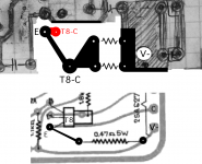
I had a similar bias problem years ago and traced it to my layout and I think yours has the same problem.
you have to feed the output transistors collector from the drivers emitter and not from any other point closer to the 0R33/5W resistors.
I have highlighted the difference between your layout and the original pcb.
hope this helps
regards
james
you have to feed the output transistors collector from the drivers emitter and not from any other point closer to the 0R33/5W resistors.
I have highlighted the difference between your layout and the original pcb.
hope this helps
regards
james
Attachments
I had a similar bias problem years ago and traced it to my layout and I think yours has the same problem.
you have to feed the output transistors collector from the drivers emitter and not from any other point closer to the 0R33/5W resistors.
I have highlighted the difference between your layout and the original pcb.
hope this helps
regards
james
Hi James,
Please explain more about your issue. Did you used the same layout as hiraga designed or you made your own layout?
Please be more explicit about your issue and the solution. I want to know.
Fab you are the best. Thank you very much for the clear response.
Monday i will do just that.
What kind of winding do your trafo had? Was it bicafillar winded to have equal impedances an voltage on the secondaries or you buyed and classic continously winded?
Is the amp influenced by this fact?
Hi Sergiu
You are welcome!
I have used a standard toroidal transformer from Antek. As long as the secondaries are the same it should work fine.
Good luck
Fab
I had a working L'30W with the original pcb then decides to make my own for the to3p transistors, the bias was way to high, checked everything and eventually change the wiring of the output stage as detailed in my previous post and the bias was right.
my layout was smaller than yours and a little more idiosyncratic, but has been working for years now.
If I can find my old layout I will post it
regards
james
my layout was smaller than yours and a little more idiosyncratic, but has been working for years now.
If I can find my old layout I will post it
regards
james
Hello,
Today i have done the followed modifications (in steps):
a) undo everything=> 0,834v bias..🙁(
b) increase 1k8 to 1k8+2*220R per rail=> 2286ohm per rail (measured) => 0,813v bias the bias is steady (with 1k8+1k/1w trimpots in this position it fluctuates abit);
c) decreased the 1k5 to 1k1 => 0,79v bias
d) increased 33k to 43k plus the above modifications resulting the following:
-- +0,810v &-0,771 across the 1k5 now is 1k1
-- +0,622 &-0,602 across the B-E of the 2sa1837/2sc4793 driver
-- +0,778 & -0,776 across the 0R33 bias resistors
Am i missing something?
Do i have to put resistors in series with the output trannies Base because of the high beta of the drivers?
Last edited:
- Home
- Amplifiers
- Solid State
- Hiraga 20W class A