I had a working L'30W with the original pcb then decides to make my own for the to3p transistors, the bias was way to high, checked everything and eventually change the wiring of the output stage as detailed in my previous post and the bias was right.
my layout was smaller than yours and a little more idiosyncratic, but has been working for years now.
If I can find my old layout I will post it
regards
james
Thanks James,
I have done this too and leaved this as you said on the whole day today. In the above results is included this addenum too. Cannot go lower with the bias..
Last edited:
Please help!
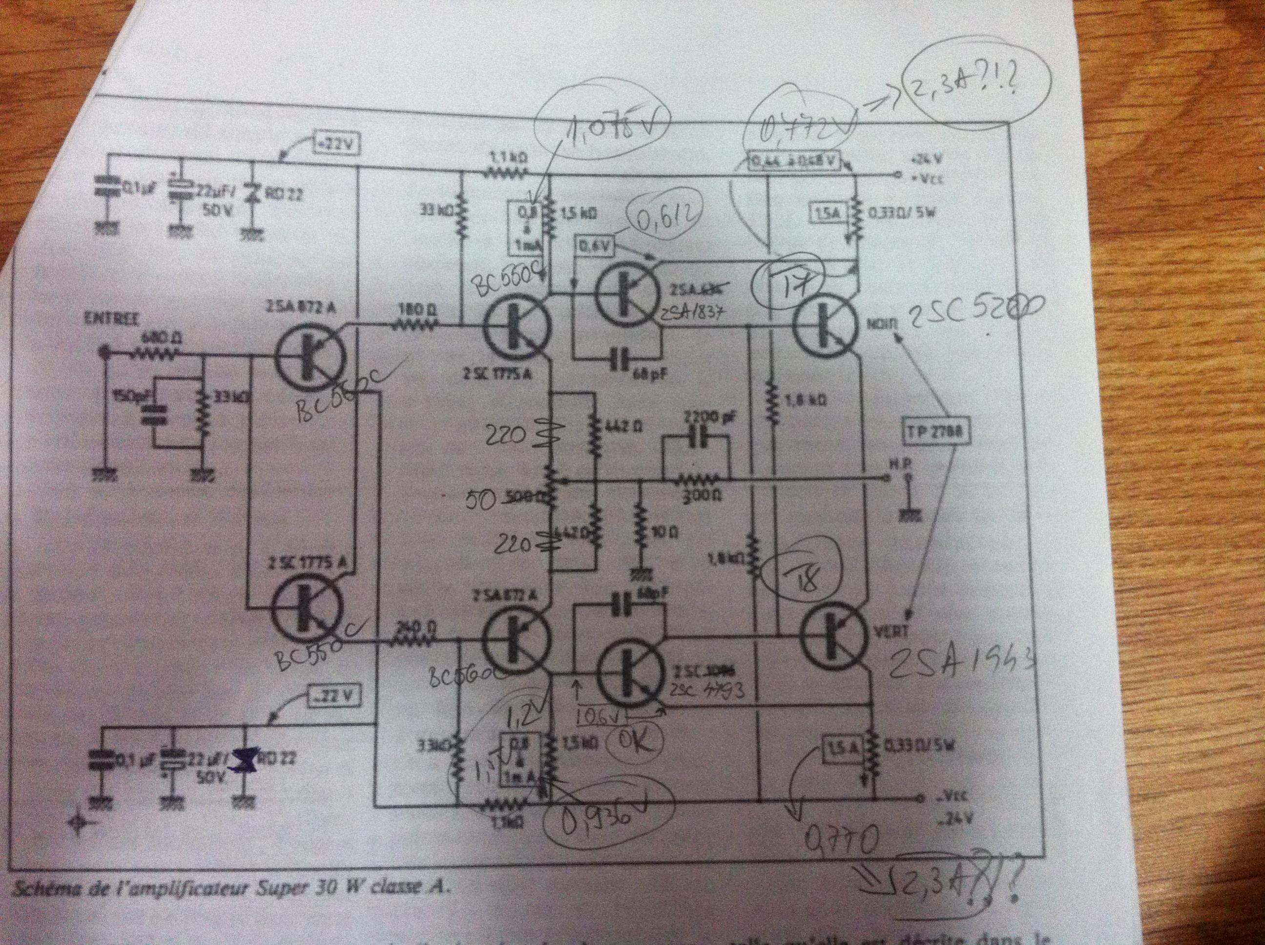
Now i lowered the 1k5 to 680ohms. The bias goes down to 0,734v and now i have 0,6 mA at the buffers collectors. I decreased the 33k to 26k and the drivers bias is now 0,94v across the 680 ohm (1,4mA--too high--needs readjust) and the bias across the 0R33 goes back to 0,843v....😡
Please help!
Now i lowered the 1k5 to 680ohms. The bias goes down to 0,734v and now i have 0,6 mA at the buffers collectors. I decreased the 33k to 26k and the drivers bias is now 0,94v across the 680 ohm (1,4mA--too high--needs readjust) and the bias across the 0R33 goes back to 0,843v....😡
Please help!
The 0r33 resistors are very hot (cant touch them). Is this because of the hight bias?
Last edited:
Hi sergiu
In the Hiraga 20W amplifier the output pair is a darlingnot, "seen" as one transistor.
The bias is set with the 1k5.
So parallel the 1k5 with a 5k potmeter, turn it to zero (really) on both sides, then gradually increase the resistance until you have the correct power (amp) flowing. Personally I'd go for 1,5 Amp. That is already a lot and gets everything hot.
When doing it this way, first ensure your resistor network in the feedback path is equally set for both halves (the 50 or 500 ohms) in the middle position.
Then make a final trim to the DC point (0,0 V) with the 50/500 ohm pot.
This simple procedure is from the F5 by mr Pass 🙂 It always works. You can even leave the pots in place if they have good quality.
turn it to zero (really)
This will not blow my driver stage away?
I'll try this tomorrow.
Thank you very much.
This will not blow my driver stage away?
I'll try this tomorrow.
Thank you very much.
Last edited:
I would just add - to use a dual gang potentiometer with 4 clip leads soldered to it to adjust the bias. I used 100 kOhm linear potentiometer Then you can find the correct value very quickly and easily.
Once this done turn off remove and measure the potentiometer and calculate the required fixed resistor value.
The output stage resistors 0.33 or 0.47 need to be minimum 5 W rating or they will run very hot.
Once this done turn off remove and measure the potentiometer and calculate the required fixed resistor value.
The output stage resistors 0.33 or 0.47 need to be minimum 5 W rating or they will run very hot.
I would just add - to use a dual gang potentiometer with 4 clip leads soldered to it to adjust the bias. I used 100 kOhm linear potentiometer Then you can find the correct value very quickly and easily.
Once this done turn off remove and measure the potentiometer and calculate the required fixed resistor value.
The output stage resistors 0.33 or 0.47 need to be minimum 5 W rating or they will run very hot.
I use 4 x 0,33/3w metal oxide resistors (per rail), two resistors in series paralleld with the other two ones. Doesnt this means that i have (0.33+0,33)*(0,33+0,33)/0,33*4=> 0,4356/1,32=0,33ohms per total at 12w cumulated.
Am i right?
If yes why do they get hot?
If not, whats the real wattage of this arrangement?
Last edited:
I would just add - to use a dual gang potentiometer with 4 clip leads soldered to it to adjust the bias. I used 100 kOhm linear potentiometer Then you can find the correct value very quickly and easily.
You mean 100k double pot for the 33k, am i right?
Daniel, i seen on your link from your avatar that you are the lucky colleague that has done a real "monster super class a 58w", why did you use 1k8 carbon resistors instead of metal oxide. Dont they go wild with the impedance when they get hot?
I see that you only altered the 1k5 and 33k resistors. Did you altered other resistors like the 1k8 to fine tune the final stake? (Just curious)
Do you remember what beta value has the input trannies and drivers?
The 2sa1943/2sc5200 are with the O suffix for beta (the highest beta) or other suffixes?
I want to get as much details as i can to know if i'm on the right path with my amp.
If you can answer to these questions i will be very gratefull Daniel.
Thanks in advance.
Sergiu
Hi Sergiu,
Yes I used 100k clipped onto the 33k resistors to set the bias.
12W should be fine.
If you have 0.8 V across 0.33 Ohm you will have approx 2.424 A which will give approx 17.8 W based on P = I^2*R.
Beta was approx 400-600 range for input stage, VAS was running really hot, can't remember the Beta value for those. The output stage was also running hot beta was approx 120-180 from memory.
I used 1W carbon due to the size after measuring the temperature effect of these resistors this improved the stability of the amp.
I hope this helps
- Daniel
I use 4 x 0,33/3w metal oxide resistors (per rail), two resistors in series paralleld with the other two ones. Doesnt this means that i have (0.33+0,33)*(0,33+0,33)/0,33*4=> 0,4356/1,32=0,33ohms per total at 12w cumulated.
Am i right?
If yes why do they get hot?
If not, whats the real wattage of this arrangement?
At 3 watts it gets them to above 200 degrees 😱. It is a theoretical value when will it be destroyed.
The best thing is to have a single higher watt reistor imho
At 3 watts it gets them to above 200 degrees 😱. It is a theoretical value when will it be destroyed.
The best thing is to have a single higher watt reistor imho
Yes you are right but if you have say 3x1ohm/3-6w in parallel, i thought that i will dramatically minimase the noise of the resistors, have tripple wattage at a small space ocuppied.
I saw that when i lower the bias the temp across them is lower (I can keep my fingers for 3-4 sec on them altought tey are hot). After the final adjust I would measure the temp with my MM sonde to see what the real temp is.
I have radiators on the pre stage and those are abit warm but not hot...
Hi sergiu
In the Hiraga 20W amplifier the output pair is a darlingnot, "seen" as one transistor.
The bias is set with the 1k5.
So parallel the 1k5 with a 5k potmeter, turn it to zero (really) on both sides, then gradually increase the resistance until you have the correct power (amp) flowing. Personally I'd go for 1,5 Amp. That is already a lot and gets everything hot.
When doing it this way, first ensure your resistor network in the feedback path is equally set for both halves (the 50 or 500 ohms) in the middle position.
Then make a final trim to the DC point (0,0 V) with the 50/500 ohm pot.
This simple procedure is from the F5 by mr Pass 🙂 It always works. You can even leave the pots in place if they have good quality.
Hi Triode,
Thanks for the advice. I just did that 5 min ago and this takes the bias down to 0.67 and 0.35V across the "1k5" (1k5+5k trimpot)...
Cannot go lower than this... If i go to minimum value (0ohm at 1k5) i have 0.82v bias 🙁
And this value is with 2.2k instead of 1k8.
😱😱😱😱😱😱😡😡😡😡😡
You need to check your layout, specifically resistor values and transistor orientation I think either that or you have an issue with a pair of transistors. This is my gut feeling but it is hard to diagnose without measuring more.
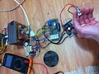
Can you take a photo of the board only in its current configuration perhaps we can help
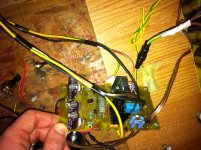
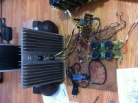
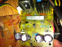
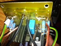
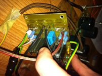
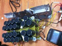
OK,
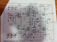
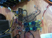
Here we are (from left to right):
1) the modified schm that you used
2) actual measurements
3) all the nest + the psu for the 24v at the input 🙂
4) soft start and a little "trick" for using that illuminated button
5) radiator and the nest
6 &7 the front of the amp
8 & ( the back of the amp
Attachments
-
 IMG_3005.PNG29.8 KB · Views: 482
 -
 IMG_3007.jpg763.7 KB · Views: 721
 -
 IMG_3009.jpg749.2 KB · Views: 446
 -
 IMG_3013.jpg653.2 KB · Views: 161
 -
 IMG_3012.jpg701.1 KB · Views: 163
 -
 IMG_3010.jpg872.1 KB · Views: 410
 -
 IMG_3014.jpg649 KB · Views: 657
 -
 IMG_3015.jpg584.3 KB · Views: 145
 -
 IMG_3016.jpg519.7 KB · Views: 147
Last edited:
And here is the rectifier + CrC for the +-25V output (2X484.000uF/35v psu's each, one 0.484F for each channel).
Attachments
Last edited:
Is it easier to type and/or to read 0.484F, or 484mF, or 484000uF, or 484k uF?484k uF for each channel
My opinion is that the fewest key strokes also equals the easiest to read and the easiest to understand, i.e 484mF for me.
Any other viewpoints?
Is it easier to type and/or to read 0.484F, or 484mF, or 484000uF, or 484k uF?
My opinion is that the fewest key strokes also equals the easiest to read and the easiest to understand, i.e 484mF for me.
Any other viewpoints?
Sorry. I was in a hurry. I modiffied now. 😱
- Home
- Amplifiers
- Solid State
- Hiraga 20W class A