It is true 15032/33 is bit different from 15030/31.
MJE15032/33 is better in this case. Suitable for +/-28 Volt supply.
MJE15032/33 is better in this case. Suitable for +/-28 Volt supply.
FWIW I did build the Hiraga (well 20 years ago) originally in a not so good looking but cheap metal enclosure. I did not know what to expect from the sound so I did not want to spent too much money on peripherals. When it turned out whey better then my expectations I build a proper wooden enclosure for it with no shielding whatsoever and after I did the transfer from metal to wooden case the soundstage became almost twice as big. Low level detail was much better and the amp was still dead quiet. No noise, no hiss even on 116 dB/w/m horn tweeters.
Building the hiraga 20 w with 25 v supply.Input transistors for the Hiraga 20 w hard to find. Could anyone advise if i could use a BC 639 and BD640 instead or should i use BC 550C/560C.
I meant, in my previous request for the Hiraga 20/30 w class A, the input transistors to be BC 639/640 OR BC 550/560.The original input transistors are near impossible to find.
I remember in the original paper, Hiraga said the input pairs are not the most critical. [the output pair is]. He even mentioned the BC550C. But do test them for similar Hfe and voltage Vbe.
Thanks for your reply, I have just completed a pair of these Hiraga amplifiers and was amazed with the sound. I use a regulated power supply capable of supplying the required current and using transistors that i had available i can confirm that this simple amp is one of the very best as far as sound quality is concerned.
I had no problem in setting the bias current and the DC offset. The transistors listed below complement the circuit and they do the job. Adjusted the 47k bias resistor to give around 380 mV measured across the 0.33R resistors at 30V. I got it right at around 34.3k.
•The use of a regulated power supply is highly recommended as with it, the amp is extremely quiet, no hum etc.
•Transistors used for the output is the 2SA1942 and 2SC5200
•Drivers BD237 and BD238
•Inputs BC258 and BC630.
Questions for Triode_al
Hy triode_al,
If we use the C termination for BC550/560 dont we have to modify some values for the input resistors because of the hight beta? (The B termination has Beta approx 240~500 and the C type has 450~900).
I'm not an expert but i just wanted to know because Jean Hiraga said in one of the issues the the input pair should have a Beta of approx 400 matched tranies.
Kind regards
I remember in the original paper, Hiraga said the input pairs are not the most critical. [the output pair is]. He even mentioned the BC550C. But do test them for similar Hfe and voltage Vbe.
Hy triode_al,
If we use the C termination for BC550/560 dont we have to modify some values for the input resistors because of the hight beta? (The B termination has Beta approx 240~500 and the C type has 450~900).
I'm not an expert but i just wanted to know because Jean Hiraga said in one of the issues the the input pair should have a Beta of approx 400 matched tranies.
Kind regards
Because those transistors has higher Beta you do not need mode anything.
Remember the original 2SA872 and 2SC1775 had high Beta. 500-600hFE depend which company produced and usually advised to use E grade
Greetings
Remember the original 2SA872 and 2SC1775 had high Beta. 500-600hFE depend which company produced and usually advised to use E grade
Greetings
Would like to rectify typing error in my previous post.
Input transisors i had available and used sucessfully are BC258B and BC 639.
Input transisors i had available and used sucessfully are BC258B and BC 639.
Because those transistors has higher Beta you do not need mode anything.
Remember the original 2SA872 and 2SC1775 had high Beta. 500-600hFE depend which company produced and usually advised to use E grade
Greetings
Thank you very much gaborbela.
Please help
1.Did anyone tried the Super class A with cap multiplier?
What differences have you noted between CM and a classic PSU (CLC recomended by Hiraga) in terms of sound reproduction (dynamics, clarity) and ripple?
I want to hear some impressions about this mod because i want to know in wich PSU to invest for this amp.
I'm interested in "Mr Evil Cap Multiplier", what do you all say?
2. Did anyone tried to do a second psu just for the input? What differences made?
3. What trannies should we use for the output stage because the 2sa/2sc pair are fake in my country and very hard to find?
Thanks in advance
It really depends on whether the PSU can supply the transient current that the speaker will demand.
An 8ohms speaker will demand more current than an 8r0 resistor does.
A PSU that performs well on the test bench in supplying maximum output into a resistive dummy load, may be totally inadequate in driving a real speaker.
Single full range speakers typically draw 1.5times more current than the equivalent resistive load.
Two way and more complex speakers with many reactive crossover components can draw at least double the current of the equivalent resistor. Some fast music transients with a particular "shape" of output voltage can make the speaker demand three times to 5 times the current that the equivalent resistor would draw.
The PSU AND the amplifier MUST be designed to meet transient current demand.
Many "clever" low ripple supplies cannot do this. They fail.
Hi, here is my Amp its the 20w Version, its using a 12v to 24v step up power supply and I cant bias very High Without having a fan On it at the moment. Until I get some heatsinks. Ive heard it biased 0.40v over the source resistors and sounds really good. But as you see the components are not that good. Any comments on people who know ? I guess I can replace resistors with better and make a better Power Supply.
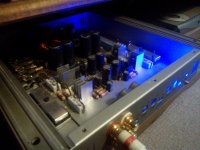
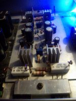
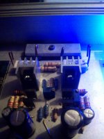
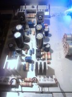
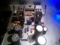
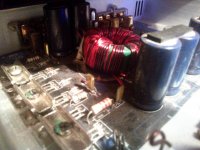


Hey, I have 0.47Ohms Resistors and 0.51V across them.
How high In theory can I bias ? I presume I can go up to about 0.70 Volts
My Outputs are 2sc5200 and 2sa1943
Do I need to change any components to make bias higher or do I just increase from 0.51v to say 0.6v
Just wondering If anyone can help, Thanks
How high In theory can I bias ? I presume I can go up to about 0.70 Volts
My Outputs are 2sc5200 and 2sa1943
Do I need to change any components to make bias higher or do I just increase from 0.51v to say 0.6v
Just wondering If anyone can help, Thanks
Last edited:
You can bias as high as the output devices can survive the extra temperature.
Once your bias is above optimal ClassAB, then when peak current exceeds the ClassA current limit, the amplifier will create crossover distortion. That crossover distortion will be worse than optimal ClassAB crossover distortion.
If your peak current is below the ClassA limit, then you don't have any crossover distortion.
- Home
- Amplifiers
- Solid State
- Hiraga 20W class A