gaborbela,
Thank you very much for the schematic. This is very kind of you. I should have both On Semi transistor types. Since I saw it on ...stigerik.. site few years ago.
Thank you very much for the schematic. This is very kind of you. I should have both On Semi transistor types. Since I saw it on ...stigerik.. site few years ago.
Hello
Your welcome!
Here is these good quality PC board, if you interested or if you want to produce yours I will look it up.
Stereo amplifer PCB Hiraga super 30W class A !!! | eBay
Someone from the forum purchased these PC board and great quality.
Schematic is same minor change.
You still can use the schematic I posted even with these PC boards.
Greetings Gabor
Hello
I tried to answer to your PM but it didn't went on so I lost the answer.
Please do not change under any circumstances the 2SA782 &2SC1775 BJT-s.
Please try to look up the lay out and the rest of the info, I posted several time on the forum. Probably I deleted because I do not find them.
Greetings Gabor
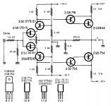
Yes indeed: Fig. 2: Modified version, class A, 60 Watts, using V-Fet transistors at the output
Hello
I tried to answer to your PM but it didn't went on so I lost the answer.
Please do not change under any circumstances the 2SA782 &2SC1775 BJT-s.
Please try to look up the lay out and the rest of the info, I posted several time on the forum. Probably I deleted because I do not find them.
Greetings Gabor
Gabor,
though you are pertinent (DON'T 😱), but .. . . is 2SA940/2SC2240 an option? I have seen this pair as a replacement in Le Classe A - but I can't find the Rbb. I bought two lots of both, match well. Intend to use these.
The commonly seen BC549/BC559 etc has a higher Rbb, in the order of 20 ohms. But they do have a flat Hfe, which is important too.
Just searching on the net, I found 2SA1316 with an Rbb of 2 ohm, and a Cob of 6 pF. I bought some, measure well, but I can't find the complement 2SC3329.
[I find the prices for 2SA782/2SC1775 just too steep] 🙄
The circuit boards of Jims audio are good: plated through holes. Thick copper. Military grade. You need a good soldering iron!
Hello
Look I know after my experience what I advise. You can take it or you can try to replace those BJT-s and after start all the endless research.
If we would talk here BC550C & 560C right away I would say replace it wit 2SK170BL & 2SJ74BL. Great improvement.
Since I tried several other type BJT and after I went back to use my short cut leads over soldered orig BJT I know it worth to buy them if you have source and you have no more headache.
I have a circuit I want to test someone mod it lot of LED, other type BJT etc I still I test it with the orig 2SA782/2SC1775.
It is possible to replace those BJT? Yes I don't say not. I built several Hiraga.
The problem these amp very sensitive every parts U use plus the PS is very important to.
If you want have a peace of mind at least test one side with the orig another side replace it ans com pare them again and again. Let us know if you find something close (sound wise) to the orig please.
Greetings Gabor
Yes indeed: Fig. 2: Modified version, class A, 60 Watts, using V-Fet transistors at the output
Hello
I wanted to try that V-Fet type. Forget it. Even if you get the orig V-Fet for horrible price the measurement no longer much with the data.
Someone get those I think (I'm not sure but not Ebay product) from Mouser , he did some measurement , after returned to the seller (company). I read that and I'm not willing to pay for those ancient parts $60/each or so.
Greetings Gabor
I will use 2SK175, 2SJ55 as I have a bunch of them and they work very well in my F5. The schema remains the same this way. The gate voltage will be around 1,6 V plus the voltage across the emitter resistance of 1 ohm at 1 ampere (1 ohm in this diagram; in the common BJT output there is o,47 ohm or lower).
Suggested 2SA940/2SC2240 transistors by triode_al are available from MCM.
2SA940 - $1.65
2SC2240 - $0.40
2SA940 - $1.65
2SC2240 - $0.40
Hello triode
Please after you tested let us know how it work out. Thank you😀
I prefer the sound of the Fet, many years I was interested on that schematic but not with those old V-Fet.
Also one day I will test the LeMostre mosfet version.
I made the PC boards but now I'm busy with other project.
I post the schematic here if someone interested........🙂
Greetings Gabor
Attachments
Hello triode
Please after you tested let us know how it work out. Thank you😀
I prefer the sound of the Fet, many years I was interested on that schematic but not with those old V-Fet.
Also one day I will test the LeMostre mosfet version.
I made the PC boards but now I'm busy with other project.
I post the schematic here if someone interested........🙂
Greetings Gabor
That's a nice combination of Le Monstre and the Le Classe A variant of the Sony Farlington.
I plan to use HIT667, + HIT647 as drivers. That must be good enough for the input capacitance, there is no real current like with a BJT output.
post571.
the R9/R10 junction connects to the feedback node.
Does it need to?
What does this extra connection achieve?
the R9/R10 junction connects to the feedback node.
Does it need to?
What does this extra connection achieve?
Hello Andrew
Probably a mistake, I have to take a look at the orig LeMonstre.
I didn't designed these circuit or worked on it.
All do I made the PC boards ready.
Thanks one more time
Greetings Gabor🙂
Probably a mistake, I have to take a look at the orig LeMonstre.
I didn't designed these circuit or worked on it.
All do I made the PC boards ready.
Thanks one more time
Greetings Gabor🙂
Hello
Yes it look like a error in the circuit com pare to the orig Monster!
Thanks one more time.🙂
Now I have to pay att. on the PC board to...
The lay out need to be rescale when you printed out!
Greetings Gabor
Yes it look like a error in the circuit com pare to the orig Monster!
Thanks one more time.🙂
Now I have to pay att. on the PC board to...
The lay out need to be rescale when you printed out!
Greetings Gabor
Attachments
I see the original connects the same two resistors to Audio Ground. Again the same question: does it need to?
Hello
Good question.I built that way a couple times, to be honest I never kept the Monstre more than couple month in my system.
I do not like that sound, to precise (almost clinical) with good CD sound OK but most of the time the sound is thin, not my cup of tea.
Greetings Gabor
Good question.I built that way a couple times, to be honest I never kept the Monstre more than couple month in my system.
I do not like that sound, to precise (almost clinical) with good CD sound OK but most of the time the sound is thin, not my cup of tea.
Greetings Gabor
In the original the cascode bias goes to ground.
With due attenuation of the feedback (220 ohms/10 ohms á Le Monstre and maximum signal of 10 peak) this means that the Vds swings one volt underneath the cascode. That is OK.
With a higher voltage, the Vds starts to swing more. At a certain point (like in the F5 cascode!) there is 5 volts swing on the Vds - to much imho, the whole sense of the cascode disappears, except for the dissipation/heat.
So Gabor,
My reasoned suggestion: connect the bottom of the bias divider to the 10 ohms of the feedback.
[The all BJT Le Classe A don't have a cascode]
With due attenuation of the feedback (220 ohms/10 ohms á Le Monstre and maximum signal of 10 peak) this means that the Vds swings one volt underneath the cascode. That is OK.
With a higher voltage, the Vds starts to swing more. At a certain point (like in the F5 cascode!) there is 5 volts swing on the Vds - to much imho, the whole sense of the cascode disappears, except for the dissipation/heat.
- (The sonic reason is that it decreases the capacitances of the input JFets and makes them more transparent)
So Gabor,
My reasoned suggestion: connect the bottom of the bias divider to the 10 ohms of the feedback.
[The all BJT Le Classe A don't have a cascode]
Hello
So you say to use the connection at the mosfet version it was correct. Connect to the ground!? Like the schematic at the post 571?
Please advise if I understand it well. All do I want to go a bit higher PS voltage. About 17V rail voltage but I still do not think that extra 5V will do 5V swing.
Greetings Gabor
- Home
- Amplifiers
- Solid State
- Hiraga 20W class A