
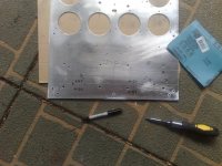


went to the hardware store today....
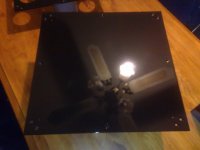
black gloss is on just have to wait for it to dry and it will be time to build this thing. (unless it needs some more paint / clear coat or something...)
PS: Hope this is enough progress to keep you happy for a little while Eduard 🙂
PPS: i am still jealous of the weather in Nth Sweden Lineup
-Dan
black gloss is on just have to wait for it to dry and it will be time to build this thing. (unless it needs some more paint / clear coat or something...)
PS: Hope this is enough progress to keep you happy for a little while Eduard 🙂
PPS: i am still jealous of the weather in Nth Sweden Lineup
-Dan
Attachments
Hello Daniel,
I didn't see you mentioning my name in the last post. I was just thinking your diy interest did go down. Mine actually is going down. Building things from start untill the end just doesn't appeal to me anymore. Keep collecting parts and ideas but the building itself. If you give me the dimensions of that topplate. I can make it in 3 hours in stainless steel. I would make it from one piece including the four sides. Would need help for the bending and welding so then it will take a week or so. For 30 euros or so you could get it electrostaticly painted if you are willing to wait untill the company will have your favorite colour in use for a big quantity. Putting on the paint will just take a 3 or 4 minutes then 2 hours in the oven and you are ready.
Usually i will get stuck when 15% is done. I think i should pay someone to finish all these projects and then sometimes just spend some time on changing a cap . I hope you did decide to keep the chokes in your Hiraga. You changed your avatar. Maybe find a picture of Mr Jean Hiraga. In Scandinavia there were a lot of people who did build things designed by Hiraga. Greetings, Eduard
Hi Eduard,
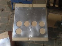
I will be putting another coat of paint on the chassis in the next couple of days and then its time to assemble the amp 🙂
So far i have all the pieces ready I am just organising the inductors for the supply, it may get run at first without them and measured/listened to then run with them and measured/listened to, so i can see/hear the "real world" effects.
-Dan
http://www.jean-hiraga.com/uk/produits.htm#
Jean Hiraga site. if anyone is interested.
soon to come -amplifiers ???
-Dan
Jean Hiraga site. if anyone is interested.
soon to come -amplifiers ???
-Dan
HI
I tried that schematic and for me didn't work out well .
There is a another schematic (the original not the modified and that sound much better .
Also I use ON semi drivers and power transistors I preffer those over the original ones .
The sound much clearer more bass al together is a very good amp .
Regards
Attachments
Hello Gaborbela,
what onsemis parts did you use ?
thats is actually the same schematic i used expect for the output pair, adj. bias and decoupling of the supply leads.
however all the transistors i used are originals expect the output pair
(i used toshiba 2sc5200/2sa1943)]
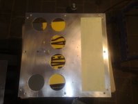
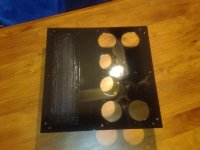
here is the second coat of paint for the chassis.
what onsemis parts did you use ?
thats is actually the same schematic i used expect for the output pair, adj. bias and decoupling of the supply leads.
however all the transistors i used are originals expect the output pair
(i used toshiba 2sc5200/2sa1943)]
here is the second coat of paint for the chassis.
Attachments

you'll soon be finished
if keep on working every week
i took a look at your PCB with everything mounted .. transistors etc.:
http://www.diyaudio.com/forums/attachment.php?s=&postid=1576462&stamp=1217728407
amazingly clean and so very few parts
for being an amplifier that can have such good sound & performance
thanks Hiraga 😎
Hello,
One of the modifacations that were done here was interrupting the dc voltage tracks on the circuitboard and give the input and output stage their own cables arriving from the big power supply caps.
Also replace those 2 1k8 resistors with something like kiwame, mills or so. Mines were changed into two watt Allen Bradley. There weren't so much audiophile resistors those days ( at least 20 years ago) However the resistors supplied with the kit in Pareis those days were Shinkoh tantal. The 500ohm pot was Cosmos brand. One of the advantages of this design is that there aren't so much parts so you should use the best parts available. It is true that even using standard parts it will surpass a lot of others because their parts are even lower grade. Greetings, Eduard
HI
You may use the similar schematic from the UK site but please take a look at the input .
These one use 22V sender diode not 13V .
About the transistors please write you e-mail address .
I spent hours and days until I found better transistor than the original .I do not want to share every body .
One more think I use capacitance multiplier power supply from ESP site it is much better for me than the regular power supply .
Regards
- Home
- Amplifiers
- Solid State
- Hiraga 20W class A