Hello Daniel,
They say it isn't that deep if you believe the people on this site. The big onken has some more hertz deeper down. BUt this one has about 103 db /1 watt efficiency and the upper part of the bass cabinet does function like a horn so it will give a better marriage with the tad 2001 which is of course a horn as well.
The bass can be made a little deeper attaching the so-called wings to the cabinets. Someone in Holland did do that and he told me is a rather big change. But i don't like the aesthetics to much of this modification. Because the cork on the bins has been covered by varnish that did change after about 16 years of daylight it will be hard to make the wings the same colour.
Right now in the proces of changing a little bit to my current power amps so it will take some time before i will do something with wings.
Greetings, Eduard
P.s these vots have never been powered by anything more than an ef86 plus el84 line amplifier with output transformer and at the input a lundahl transformer so it can be driven by the preamp thas has a symmetrical Tango outputtransformer.
Hi Eduard,
I see what you mean.
Back to the Hiraga power supply choke issue.
Do you know if the choke needs an air gap in this case, I realise that the choke will be predominantly handling dc however the ripple component woudl be better removed with a gapped or ungapped core ?
I have measured a lighting choke today and it is 200mH @ 3A, the core appears to be gapped but the core handles predominantly AC I think perhaps the chokes will be out of the question with my current chassis based on the size of this unit !!!! (~10CM^3)
I may be able to squeeze in some chokes but certainly not this size.
-Dan
Hello Daniel,
I am not a technician at all especially concerning electronics. But the dimension of the air gap together with the diameter of the wire and the seize of the core will '' determine '' the number of millihenries.
The task of a choke input would be really heavy in a choke input for a hiraga with 1,5 A running constantly trough its power transistors all the time.
As stated before if i will be ever going back to solid state i would get a choke-input. You are using 200000 microfarad directly after the rectifiers, this will give them and the transformer a pretty hard life. Did you pay a surplus price for them? If yes i would try to reduce the value of the ffirstone.http://www.selectronic.fr/upload/produit/pagecatalogue/5-32.pdf
These are the kind of caps used by the french in the eighties. This is philips but as you can see it is the successor of the sic safco co38 and co39 style. I don't know if the original French la maison de l'audiophile shop still exist but they were selling the 100000mf 40volts 330000mf 25 volts and the 68000mf 25 volts types. They were types with long life, low or extreme low internal resistance and capable of delivering lots of energy. The hiraga transistor designs are very sensitive to the quality of the power supply so every change should be heard. Swictching from your current situation with no choke at all to a real choke-input ( if possible within your chassis) will certainly transform it into a class of its own.
With my current power amps i use a bleeder resistance with a value that will keep a current flowing no matter if the tubes are in or not. Pulling them out doesn't have an effect on the voltage measured. This cannot be done with the hirage because you will need a huge bleeder resistance and a huge choke. With 200millihenry used as a choke input you will certainly get a voltage drop but it will not be a true choke-input i think like you can make with a poweramp like mine because of the high current involved.
I just did consult one of my philips books. They say the size of the airgap will determin the inductunce under different loads.
I will try to attach the two chokes i did mention before.
I think we should connect to the people posting in the pass labs. Allthough they also didn't use lots of henries so far,
Greetings, Eduard
Attachments

hello,
In my last post i did say that getting a choke-input for the hiraga will be hard. I did look for the information i did use for the power amps i am actually using. For a choke-input it would be absolutely necessary to have a bleeder resistor that will draw some current no matter what will happen. These 2 resistors will get hot so they better be the aluminium wire wound type screwed tightly to the chassis or some kind of heatsink.
The dc voltage available will drop a lot.
I just did read on a French website that Jean Hiraga is working on a new power supply for le monstre. I don't know where and if they will be available commercially.
http://www.jls-info.com/julien/audio/hiraga.htm
http://pagesperso-orange.fr/audiotechno/html/realisations.htm
The first link, look how clever the circuit has been mounted to the heatsink. I mean short connection of the pwer transistors and the input. The emitter resistors will heat the up the heatsink even more so i would go for mills air cooled.
The second link . take a look at the chokes ( c-core) used in the big kaneda. He also did use chokes for the 8 watt but he forgot the value. The c cores in the kaneda are different than the ones i did buy at that time.
You see using using chokes in transistor design is rather popular.
Happy reading?? at least you can take a look at the way it is build.
Greetings, Eduard
thats is some interesting stuff Eduard,
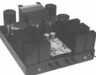
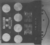
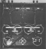
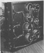
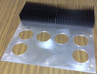
Here are some pics of what sort of thing i am doing,
this one is of another chassis layout you may have seen with the 0.2mH chokes on the top plate.
I think i will use a similar size choke on the interior of the chassis
(60mm height)
Here are some pics of what sort of thing i am doing,
this one is of another chassis layout you may have seen with the 0.2mH chokes on the top plate.
I think i will use a similar size choke on the interior of the chassis
(60mm height)
Attachments
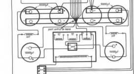
here is approx the layout apart from the values.... i am kind of mixing and matching here basically using the "le class A 20W" supply with more capaciatance and different volts, with inductors in place of the filter resistors (hopefuilly if they fit !!!!!!!!!!!)
Attachments
Hello Daniel,
The first photo is the 50 watt kaneda and all the others are hiragas. I did take a closer look at your chassis again.
I think i did mention it before you can create some extra space by mounting the chokes on the inside of the top plate ( maybe using stand-offs and a little mounting plate) Everything above 60 mm will pass through a hole in the bottomplate to allow some extra space. No parts will be mounted on the bottomplate itself. This hole could be covered by a small box-like construction. But if there are electrical wires uncovered it might stay open to allow some extra airflow.. Maybe mount the round transformer on the inside and make a circular hole in the bottomplate and move the chokes to the upper part. this way they could be bigger . I think , i mean i am sure doubling the va of the transformer will give less effect then adding 2 chokes.
Are you willing to sacrifice some output power by changing it into a choke-input? 23 volts dc and a current of 1,5 A with a choke-input will probably give you more life-like sound then the few extra watts created by a higher dc.
I still think 200000 microfarad with no choke input is to big for the diodes and transformer to stop them from generating unwanted noises.
I did use a resistor on the primary side to reduce the dc to 10 volts and keep the caps loaded all the time. I remember switching on the amp would make the light go down a bit. With the resistor power consumption in stand-by mode is extremely low and it will gie a longer cap life keeping in mind the huge currents involved in charging when using 1,5 farad. I remember the first time using an aluminum wirewound for this purpose but the wrong value i did make it explode( meaning the resistive element did shoot outside at one end) illustrating the current involved.
Creating a pass through in the bottom will make some extra clearance necessary by using higher feet BUT i think you need that anyway to allow maximum airflow.
I did put the circuit on the inside of the top plate and have a small hole on top to reach the pot to adjust dc offset. I remember that when they were on top , moving a door near by would change the offset not a lot but i could see it on the meter.
Sending two kilo to australia will be 19,5 euro if you have the equivalent in us dollars ( and you are afraid they will drop some more) i will offer you a new aluminium plate( 2 or 3 mm thick) rectangular or big circular holes included for just the cost of transport just to convince to to give that choke input? a try. I think you will be hooked. greetings, Eduard
That is a very nice offer, but i have found a choke which is 170-200mH and approx 1 Ohm which is just 53mm x 110mm x 66mm i can fit it 🙂
i will try it in the circuit first (outside the case to see how it goes
it is suitable for 3.2A continous at mains voltage... i need to check if the core is good enough not to saturate though
-Dan
i will try it in the circuit first (outside the case to see how it goes
it is suitable for 3.2A continous at mains voltage... i need to check if the core is good enough not to saturate though
-Dan
Hello Daniel,
I will wait for the good news to appear. Maybe open a new thread about using a real choke-input for solid state classA designs. So with values like the one you just did track. Greetings, Eduard
I will wait for the good news to appear. Maybe open a new thread about using a real choke-input for solid state classA designs. So with values like the one you just did track. Greetings, Eduard
choke-input or cap-input?
Hello ,
No reactions for a couple of days allready.
Maybe Daniel is busy listening to the merits of using chokes for his hiraga?
By the way i did remember having some power transformers with milliampere ratings for both cap input and choke input. I have been trying to find them but i think they are gone. The rating for the choke-input was higher so i guess this explains one of the reasons choke-input is sounding better. It will give the power supply an easier life.
BUT don't tell anyone otherwise the strong believers cannot buy high current surplus chokes anymore. Not the kind of chokes used on the primary side but 100 millihenry and up.. By the way i have some stock for both solid state and tube designs so will not be tempted to bid anymore. Allthough the weak dollar is making it attractive to do. Metal prices still going up so they will get more and more expensive and these things if treathed properly have a longer life than we do.
greetings, Eduard
Hello,
Did find some more information for the ones not jet choke-addicted.
http://www.qsl.net/i0jx/supply.html
Greetings, Eduard
Did find some more information for the ones not jet choke-addicted.
http://www.qsl.net/i0jx/supply.html
Greetings, Eduard
Hi Eduard,
Unfortunately no amp building on the weekend.
too much work/study/training etc.... during the weekend.
I have measured the choke I plan to use = 137mH ~3.2A capability @ 1.7-1.9 Ohm.
The only problem - it is not an air gap choke... so i would have to load test it to find out if it is suitable.
want to find out if it does actually saturate at this current level (3A).
the core is relatively large >300cm^3 volume so i am hopeful.
i will test it and let you know.
-Dan
Hello Daniel,
I think reading the link in my last post could be usefull to someone more technically advanced than me. I think they he did talk about air gap too.
I remember having some chokes that also indicate the max ac level across the choke.
I did find some measurement with the 400 millihenry 2A 4,2 ohm choke i have. All with same transformer. Current with bleeder 550ma 91,3 volt dc. With choke-input 357ma 59,4V 693ma 57,5V 1110ma 55,6V 1300ma 54,7V 1560 ma 52,7V
I think a so called swinging choke also hasn't an airgap.
I think attaching a load will show you if it is still working as a choke-input filter. I really hope it will.
Greetings, Eduard
P.s in this link you can see the line amp that i use as a power amp. The window votre page 4 will show the circuit and the first page is showing their outside. I just did miss a bid for the output transformers. Some of my chokes were made by bourderau I know someone who has a pair of them.
http://radio-france-vintage.monsite.wanadoo.fr/index.jhtml
Thanks Eduard,
I did read the article, and i noted in general for a DC choke the air gap is necessary to break the magnetic gap to avoid saturation.
I hope i have enough iron (silicon steel) to get away without it !!!!
-Dan
I did read the article, and i noted in general for a DC choke the air gap is necessary to break the magnetic gap to avoid saturation.
I hope i have enough iron (silicon steel) to get away without it !!!!
-Dan
Hello Daniel,
This thread begins looking like a personal message thread between a few people. Allthough i don't have any advantage in persuading people to go for a choke-input. It did make me read some more on this subject allover the internet. 95% of the info is related to tube gear and you can find a lot of contradictions about chokes .
Some information is related to calculations like the critical induction of a choke for a certain amount of current and a certain dc value. So just need a pocket calculator to do that.
But then people start saying use a low dcr choke, other people say low dcr will cause ringing, use a current rating 6 times the actual measured current. Now i have been using Tango chokes developped for choke-input filters and they indeed do sound better then all i did use before but they also ar the most expensive ones so far. For a non choke -input use your choice will be less critical probably.
Mounting the heatsinks horizontally will make their cooling capabilty less. Maybe add a little fan?? Will the heatsinks be mounted directly on to the alumium chassis? Then there will be some heat transfer to the other parts as well. Mounting the heatsinks on stand offs with 2 centimer length will allow airflow under them ( chimney effect Hiraga)
I will wait for the people to start using a chokeinput power supply for the hiraga. Greetings, Eduard.
P.s will just read untill there will be a real experience available here.
- Home
- Amplifiers
- Solid State
- Hiraga 20W class A