Hi Gaborbela,
What transistors did you use ?
I have used
origional 2SC1775A(E) 2SA872A(E) (hfe matched)
origional 2SC1096 / 2SA634 (NEC)
and 2SA1943 / 2SC5200 (Toshiba) output stage
-Dan
What transistors did you use ?
I have used
origional 2SC1775A(E) 2SA872A(E) (hfe matched)
origional 2SC1096 / 2SA634 (NEC)
and 2SA1943 / 2SC5200 (Toshiba) output stage
-Dan
Good to see that this wonderful old design is still around and being built.
The idea of replacing the PSU resistor with an inductor is new for this amp. The PSU of this amp is already so massive it's hard to imagine more. Will be interesting to know if the choke helps any.
One word of warning. Be careful not to overbias the output transistors. I did on my first build - the power transformer was a little "hot" and I did not adjust the bias resistors to compensate (1.8K, IIRC). The output transistors died after a few months. Pure DC on the speaker terminals.
So better safe than sorry on the outputs. 😉 Don't run it too hot.
http://www.surplussales.com/Transformers/PowerChk-1.html
Hello Daniel panomaniac and all the others,
Long time ago l'audiophile did publish a single ended solid state design with aa output transformer and a choke in the power supply. At that time i did ask them if i could use this coil in the 30 watt hiraga i was busy building. Since then they also did sell it in a 50 watt kaneda kit published in 1988. Replacing the resistor by a choke would give a cleaner dc. It is true and it also sounds better even when using 4 330000 mf capacitors.
Using choke inputs for my tube amps and preamps after having used cap input for the same ircuit i did realize it might be a good idea to do so for solid state classe A designs like the hiraga. Doing some searching on the internet i did read that Ayre company did do the same for some of their designs but they also said that they didn't do it for some design because it would be to expensive. Maybe they are using a so called swinging choke to prevent caps from being destroyed when there isn't a load during switching on the amp? If i would have to buy a pair of chokes for an hiraga i would certainly find a solution for this problem. Maybe a kind of dummy load during switching on and off? Maybe one of the technicians around here could give an example how to calculate the minimum value of a choke to be used for an hiraga amp with 1.5 amps running through its power transistors.
Using high value caps directly after the diode bridge will give it a hard time. Some people at l'audiophile did suggest not using toriodal power transformer because of their large bandwith.
Above is a link with some chokes that could be usefull. The one used in my hiraga did have a dc resistance just below 1 ohm. But it wasn't use as a choke-input filter. Maybe a coil that would be necessary for a choke input would have a higher dc resistance? Would be nice to hear about a choke-input power supply for the hiraga or the monster. Would be a real monster if used with chokes in the link above. But they have eternal life. The 330000mf caps were about 170 dollars each. If i was still using an hiraga amp and i would be sure that one of the chokes listed would give me a true choke-input power supply i would surely be convinced to make an investment of a few hundred dollars. But you will need a power transformer giving a higher voltage because it will drop considerably. Maybe in the beginning use it instead of the resistor where it will not give such a big voltage drop if their resistance will be about equal. When you enjoy it start searching for a new transformer. They say it doesn't have to be huge because the choke will act like as a kind of electronic flywheel. You will impress your friends witch such a heavy amp but only a few watts or tell them you did find a more powerfull design and just did change the circuits and ask them to guess the power rating of your new amp. Greetings, Eduard
p.s a good idea not to toast your power transistors
le Super Nemesis?
Regards
James
An externally hosted image should be here but it was not working when we last tested it.
Regards
James
Attachments
Hello,
The circuit attached is the basic nemesis. The super nemesis has 3 transistors the basic just did have one to3. in the picture there is the choke that was also used for the kaneda and the hiraga.\
Just surprised that this circuit did end up in australia. Even in europe you will not come across lots of nemesis amps. People say it looks easy, very easy but it isn't that easy to build one that will function day day out with the same quality.
Later on they did develop Le nemesis compensé using a 330 va toriod with 2 *110 volt primaries and 2* 40 volt secondary windings as output transformer. both primaries are used and only one secondary. Get the second cd-rom with l'audiophile scans mentioned in this thread earlier on and be surprised or not.
Greetings, Eduard
Please send your email address , I spent lot of time testing diferent transistor I do not want to sare to everybody .
Regards
Regards
Cool! I remember that schematic. Never built it, tho.
Had forgotten that the amp was built in a commercial version.
As for the choke, I do worry about inrush current. Would it be a problem? In the power supply article linked to above he uses a 15mH choke. That should not be hard to find - in fact I have several here, they are iron core chokes for crossovers. Got them at Madisound. They should work just fine.
But going to 200mH is going to be a lot harder.
I did use a toroidal tranfo on some of my 20W class-A builds. Cheaper, smaller and easier to find then the C-Core type. Seemed to work OK. William at the Audiophile gave me a hard time about it, but that's William. 😉
Hello ,
I never did see the commercial version of a nemisis amp. There has been a kit version including an aluminum chassis that looked like the 300b chassis offered in Paris.
Most chokes would survive the current but i would worry about the inductance not being high enough to make it work like a real choke-input. Compare what will happen in a tube-circuit. Most data sheet of rectifier tubes will give a minium induction for the choke to be used for a choke to be used in this situation.
Those louspeakerfilter chokes will not have an air-gap. I think they are not suited for this kind of heavy work.
I would like someone to use a choke-input for the hiraga. In the link mentioned in my e-mail before you can also find some other models with no photos attached. Just search for chokes.
Indeed the famous William. I never did meet anyone that did like him. haha.
The dollar still dropping or did it stop so the hiraga owners should get some american army or navy iron.
Greetings, eduard
hello,
maybe the title of the original thread should be changed so the people curious enough would get some input from people who did do some experiments concerning passive power supplies for power amps with a stable but large current flowing.
In europe there used to be quiet a lot of hiraga builders but because the transistors in the well tested designs did become obsolete and the availability of other designs people start making the others too. Especially in the early eighties there weren't a lot of kits available that could be called high class. The french l'audiophile magazine did surely start something. greetings, eduard
correct me if i am wrong but toroidal bandwidth should not be a (problem with this choke filtering and the amount of capacitance here (bypassed with smaller caps too)
perhapsd a small(ish) inductor can be wound on the bobbin of a approx 50VA E-I silicon steel core with the appropriate winding diameter.
another option is a low value lighting choke they are typically dipped in some kind of epxy covering to stop "buzzing" i measured one at approx 500mH / 3.2A but it was too large for my chassis.
-Dan
Hello Daniel
Concerning the bandwith i am just repeating what the French people were saying and they were also the ones using chokes and these enormous capacitors. I remember reading it in one of the l'audiophile magazines but which one?
In the picture a few post back you can see the size of the choke i did use.
We are talking millihenry and not microhenry. In the link to the american suppplier i did post a few days ago there are some candidates. But you would have to calculate how much inductance you need to make it work like a choke-input power supply ( critical inductance) and find out if it would be necessary to create a load whatever will happen to the amp circuit itself, just like a tube-amp situation. Because you have the ability to manufacture your own coils i would certainly try to make a pair 10 centimeters cubic seize or more.
Maybe it will force you to make a new chassis but your amp will be in a different league as well. I don't know about shipping cost of a new top plate to australia . Maybe i could help you out if you need these cap holes or big square or rectangular holes. The bigger the holes the lower the shipping cost. I did check below 2 kilo 19,50 euro
P.s It wouldn't be a bad idea to have chokes with a volume equal to that of the power transformer.
I agree withyou Eduard but i want to keep to these dimensions and i have spent enough cash on the amps chassis already !!
If i was richer and had more time maybe 🙂
I will measure the ripple under load and see what i need 🙂
-Dan
If i was richer and had more time maybe 🙂
I will measure the ripple under load and see what i need 🙂
-Dan
hello daniel,
i agree buiding a hiraga chassis a lot of time. i did allmost copy the original but i had to add rectangular holes for the two chokes as well. But i did had it made from one piece of aluminium bended two times on all four sides and then welded in the corners. Anodizing it did finish the job. Now i work with a machine to make holes in metal sheets so it is getting easier.
Now i usually make a kind of frame with some holes and the top and bottom plate would be very easy to change to change it into another amp.
If you did get the caps at surplus prices it might be a good idea to reduce the value of the first cap because the transfomer and the rectifiers will have a hard life. But if it will give you just a lower height model you will not gain extra space to have more room for these chokes. Maybe get two dead caps, empty them and put a choke inside lol. ooh i think i am a to convinced user of chokes.
I think i did mention a few days ago that one i did had to make a big hole in the bottom plate of my power amps to gain about 2 centimeters for passing a cap that was mounted on the inside of the top plate. Once you heard the effect of the chokes you will certainly find a way to install them properly. Greetings, Eduard
http://www.tpub.com/neets/book7/27f.htm
http://www.jt30.com/jt30page/micKcircuits/Choke-Input-Filter.html
http://locofonic.alphalink.com.au/choke1.htm
Hello,
I did search the internet for some additional information on choke-input power supplies . 99% used for tubegear but the priciples remain the same. There seem to be a lot of people around that were astonished by the results if it is used the way it is meant to be. greetings, Eduard
Hello,
I don't have any pics of my choke equipped power supply for the hiraga amp.
I am a computer dummy so somehow i cannot attach the scanned old style photos i have of my choke-input tube gear. I recently did buy a real digital camera so maybe i should try uploading. In the attachment you may find or not the choke-input power supply of my new to build vt25 single ended to be used to drive my tad 2001 Greetings, Eduard
Attachments
Hello,
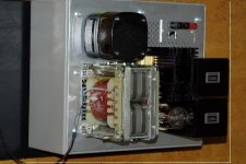
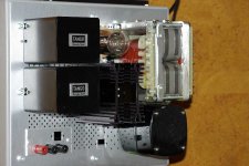
The black transformer is for the heater supply. The double c is for the high. voltage. The heathsinks are for the bleeder resistors. The amplifier itself ( double mono ) have exactly the same chassis for the amplifier itself. Only the mounting plate for the components will be different of course. The grey colour chassis are power coated stainless steel 2 mm thickness bended and welded to function like one piece being thrown away because the client did have his design altered. A pity i did just take 4 because there were at least 50 of them. A nice height allowing the mounting of big parts on the inside as well.. Maybe i will decide to go for a similar design when i will opt for a poweramp with the power supply incorporated. Still struggling to get it finished . It will be a 25 kilo ( The thing in the pic without bottomplate, transformerprotection and some parts inside was allready reaching 17 kilos)up monoraul amp to '' feed'' a tad 2001 above 600hertz with flea power.
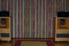
Jean Hiraga did convince many audiophiles that using high efficiency drivers is easier than trying to reach the same level with low efficiency loudspeakers driven by complicated high power solid state designs. My vot's are being driven by a line preamp with el84 and an output transformer designed in 1961 for the french broadcasting organisation. Now working with a choke-input power supply and an allen wright shunt power supply. OOOH we are way off topic. Greetings Eduard
The black transformer is for the heater supply. The double c is for the high. voltage. The heathsinks are for the bleeder resistors. The amplifier itself ( double mono ) have exactly the same chassis for the amplifier itself. Only the mounting plate for the components will be different of course. The grey colour chassis are power coated stainless steel 2 mm thickness bended and welded to function like one piece being thrown away because the client did have his design altered. A pity i did just take 4 because there were at least 50 of them. A nice height allowing the mounting of big parts on the inside as well.. Maybe i will decide to go for a similar design when i will opt for a poweramp with the power supply incorporated. Still struggling to get it finished . It will be a 25 kilo ( The thing in the pic without bottomplate, transformerprotection and some parts inside was allready reaching 17 kilos)up monoraul amp to '' feed'' a tad 2001 above 600hertz with flea power.
Jean Hiraga did convince many audiophiles that using high efficiency drivers is easier than trying to reach the same level with low efficiency loudspeakers driven by complicated high power solid state designs. My vot's are being driven by a line preamp with el84 and an output transformer designed in 1961 for the french broadcasting organisation. Now working with a choke-input power supply and an allen wright shunt power supply. OOOH we are way off topic. Greetings Eduard
Attachments
eduard said:Hello,
The black transformer is for the heater supply. The double c is for the high. voltage. The heathsinks are for the bleeder resistors. The amplifier itself ( double mono ) have exactly the same chassis for the amplifier itself. Only the mounting plate for the components will be different of course. The grey colour chassis are power coated stainless steel 2 mm thickness bended and welded to function like one piece being thrown away because the client did have his design altered. A pity i did just take 4 because there were at least 50 of them. A nice height allowing the mounting of big parts on the inside as well.. Maybe i will decide to go for a similar design when i will opt for a poweramp with the power supply incorporated. Still struggling to get it finished . It will be a 25 kilo ( The thing in the pic without bottomplate, transformerprotection and some parts inside was allready reaching 17 kilos)up monoraul amp to '' feed'' a tad 2001 above 600hertz with flea power.
Jean Hiraga did convince many audiophiles that using high efficiency drivers is easier than trying to reach the same level with low efficiency loudspeakers driven by complicated high power solid state designs. My vot's are being driven by a line preamp with el84 and an output transformer designed in 1961 for the french broadcasting organisation. Now working with a choke-input power supply and an allen wright shunt power supply. OOOH we are way off topic. Greetings Eduard
i am very jealous of your "voice of the theatres" they look really nice in that finish !!!!!
-Dan
- Home
- Amplifiers
- Solid State
- Hiraga 20W class A