Hi,
I confirm danieljw's post. I did a little experimentation and the 68 pf caps have little or no influence on sound quality, in fact I was able to do without them but no measurable (ok, with poor measurement equipment) or hearable difference was found.
It is worthwhile to experiment with various types of cap's for the 2200pf cap I think. That gave quite a bit of difference for me soundwise. Don't remember what i tried (about ten years ago) and i don't have the amp anymore. Do remember that i did not like styroflex there.
Use the caps they don't affect sound that much, not a limiting factor.
grtz
Joris
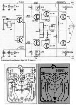
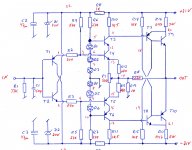
What do you think about this bandwidth on the original scheme of 20W hiraga amplifier? Is it possible?
http://www.tcaas.btinternet.co.uk/hiraga3fig8.gif
http://www.tcaas.btinternet.co.uk/hiraga3fig8.gif
The square wave looks perfect without any capacitors when simulated. I have built a couple of headphone amps with this topology, and the square looks more or less like in sim. One has to choose the right feedback resistor, and maybe use an input filtering cap.
Wherever I've read about current feedback amps it says one should not use caps in the feedback loop. Such a cap will make the amp less stable. Simulating the very circuit above shows a peak in the 12 MHz region when the 2200 pF feedback cap is added.
Wherever I've read about current feedback amps it says one should not use caps in the feedback loop. Such a cap will make the amp less stable. Simulating the very circuit above shows a peak in the 12 MHz region when the 2200 pF feedback cap is added.
@nelsonvandal:
You do simulation, I do the building.
I have built several 8Watt and 20Watt.
Every amp needed more or less compensation over the feedback resistor, to suck the needle of the square wave.
Again, check with scope recommended.
Regards
Sam
You do simulation, I do the building.
I have built several 8Watt and 20Watt.
Every amp needed more or less compensation over the feedback resistor, to suck the needle of the square wave.
Again, check with scope recommended.
Regards
Sam
OK, some real life then. Feedback resistors 4k7/1k.@nelsonvandal:
You do simulation, I do the building.
I have built several 8Watt and 20Watt.
Every amp needed more or less compensation over the feedback resistor, to suck the needle of the square wave.
Again, check with scope recommended.
Regards
Sam
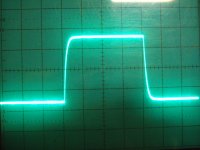
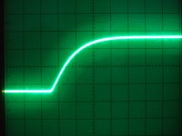
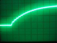
First 100 kHz square without compensation. Second magified 10x. Third magnified 10x with an added 47 pF cap in parallel with the 4k7 resistor.
Attachments
What amp we are talking about?
Regards
Sam
It's not the "le Classe A" but the same topology.
I can see your point that there's often a spike of overshooting in CF amps, and that it can be removed by adding a feedback cap. That feedback cap seems to "decompensate" the amp, and you have to add other caps (VAS local feedback and input filter) to remove the peak it causes.
Whats your oppinion on how overshooting affect the sound? I've found that a peaking amp can sound harsh. Is it the same for overshooting?
Attachments
Hello nelsonvandal,
yes you are right, overshooting sounds harsh. More than this, you have to take care for a high quality cap over the feedback resistor. I do not clean the peak
to much, so if there is still a little finger at the upper corner, I let him go.
To much compensation makes the amp slow.
Regards
sam
yes you are right, overshooting sounds harsh. More than this, you have to take care for a high quality cap over the feedback resistor. I do not clean the peak
to much, so if there is still a little finger at the upper corner, I let him go.
To much compensation makes the amp slow.
Regards
sam
Hi,guys.
What do you think about the graphic on this picture?
This is my hiraga amplifier without capacitators 2,2nF,150pF and 2x68pF.
Illustrate that my signal generator is diy also and it is not perfect.
The power supply is 2x40V with bias = 2A.

What do you think about the graphic on this picture?
This is my hiraga amplifier without capacitators 2,2nF,150pF and 2x68pF.
Illustrate that my signal generator is diy also and it is not perfect.
The power supply is 2x40V with bias = 2A.
Can someone help me i can not find transistors 2SA634 and 2SC1096 .
Which transistor will bee a good replacement for hiraga 30w?
Thanke you!
Which transistor will bee a good replacement for hiraga 30w?
Thanke you!
Hello
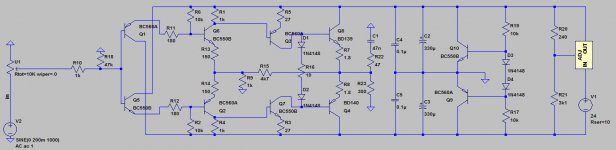
Did someone ever used these schematic .
It is very interesting with those LEDs and the extra par transistor ..
I use the orig.schematic can these be better than that ?
Any comment on these please .
Probably I will try these interesting schematic with those mods.
Greets
Did someone ever used these schematic .
It is very interesting with those LEDs and the extra par transistor ..
I use the orig.schematic can these be better than that ?
Any comment on these please .
Probably I will try these interesting schematic with those mods.
Greets
Attachments

2SA872 & 2SC1755 transistor replacement
Hello
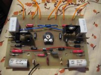
I decided to rebuild my Hiraga Class A amplifier .
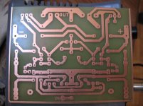
So I took the PC board layout posted a couple page back . I made my PC board , today I started to populate one .
I just realized who ever design these PC board he didn't design for the original 2SA872 & 2SC1755 .
Even do I have the original transistors I have to replace it because the PC board was design different pin out transistors .
My question can I replace the 2SA872 & 2SC1755 with BC550C & BC560C
or may be 2N5401 & 2N5551 ..These two I have at hand and the pin out match with the PC board layout .
Any help , advise welcome .
If someone tried any different transistors in place 2SA872 & 2SC1755 please let me know .
I will use 24V rail voltage
Thank you very much .
Greets
Hello
I decided to rebuild my Hiraga Class A amplifier .
So I took the PC board layout posted a couple page back . I made my PC board , today I started to populate one .
I just realized who ever design these PC board he didn't design for the original 2SA872 & 2SC1755 .
Even do I have the original transistors I have to replace it because the PC board was design different pin out transistors .
My question can I replace the 2SA872 & 2SC1755 with BC550C & BC560C
or may be 2N5401 & 2N5551 ..These two I have at hand and the pin out match with the PC board layout .
Any help , advise welcome .
If someone tried any different transistors in place 2SA872 & 2SC1755 please let me know .
I will use 24V rail voltage
Thank you very much .
Greets
Attachments
Last edited:
Complementary for the 2SA872 is the 2SC1775 not 2SC1755.
My suggestion is to insulate the legs and bend them to fit in the layout.
If you have original Hitachi's, why don't use them😀.
Can you give me the numeber o f the post wich layout you have used?
Regards
Sam
My suggestion is to insulate the legs and bend them to fit in the layout.
If you have original Hitachi's, why don't use them😀.
Can you give me the numeber o f the post wich layout you have used?
Regards
Sam
Hello masag1Complementary for the 2SA872 is the 2SC1775 not 2SC1755.
My suggestion is to insulate the legs and bend them to fit in the layout.
If you have original Hitachi's, why don't use them😀.
Can you give me the numeber o f the post wich layout you have used?
Regards
Sam
Yes you right my mistake
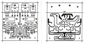
2SA872 & 2SC1775The problem those transistor pin was cut short . They were used in my old PC board .
I want to use these new PC board because I can solder direct the power transistors in the PC board .
My old PC board has to many jumpers and have to use wires to connect the power transistors .
These circuit was redesign by somebody and it use some type of cascoding .
Greets
Attachments
- Home
- Amplifiers
- Solid State
- Hiraga 20W class A