Dear wahab,
I have now taken a closer look, and the circuit looks very familiar to me. And yes, you could buy exactly this circuit as a finished module in Germany for a long time. Not exactly, but slightly slimmed down and with a switch-on delay: OCL-950 from Monacor. This is now all decades in the past.
Many thanks for the original schematic, I remember the performance - without blame.
greetings,
HBt.
That s somewhat equivalent to a diamond s buffer since the drivers emitters resistances are tied to the opposite supply rail.
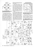
On the left is the schematic published by SGS, surely on the footsteps of Moorola and also Fairchild who made AN
using this topology, on the right is the drawing from a french review that used SGS schematic without any mod.
This topology was very popular at the time and was recycled among other by Monacor and later by Elektor as basis
for their their half baked Crescendo with a cascoded VAS, it was also used by commercial brands like Nikko, Rotel and Luxman.
As you can see it make more sense than the australian design that try unsuccessfully to drive a symmetrical VAS using
a single differential, this was done by Sansui circa 1976 but in a more complexe maneer, to summarize they inserted such a symmetrical differential between an input single ifferential and the VAS, and guess what, they called their topology diamond,
here their schematic FTR :
Attachments


A bit off topic here, but still relevant: Wahab, what should Elektor have done differently in designing the Crescendo?half baked Crescendo
Most important would have been to implement a miller compensation rather than relying on the lateral fets input capacitances
as shunt compensation, what they didnt notice is that it s way not enough to guarantee a minimal stability, indeed they had complaints from their readers that there were oscillations, so they made an update where they explained how they proceeded
and that their cure was to add yet another pair of lateral wich was supposed to increase the capacitive loading of the VAS,
rather than correcting the thing with two tiny capacitors they insisted on their flawed assumptions.
Second is that they used 65V BC546/556 in the differentials while the supply voltage was +-75V, that s litteraly
an electronic russian roulette.
Also they used 10k resistances to feed the cascodes 3.9V Zeners, that s 7mA current with 70V, so that make 0.5W to be dissipated uselessly and 1W resistances at least, while a single mA would have been way enough, but hey, they had very good typography,
and the fact that their schematics were very well drawn instillated the idea that they were as competent as their drawings,
guess that it s yet another demonstration that the clothings makes the monk.
Last edited:
Now I've understood you wahab (and we didn't really disagree at all). To be honest, I don't have the right words for the “diamond”, for me it's all just “simple circuit technology” - sometimes better and sometimes worse implemented, according to the motto: purpose fulfilled or just an appendage that is taken along but misses the actual purpose.That s somewhat equivalent to a diamond s buffer since the drivers emitters resistances are tied to the opposite supply rail.
So be it. Perhaps Pavel M. (@PMA) can give us a more comprehensive overview of all possible diamonds. For my part, I just read circuits and localize the functions - and don't need fancy names.
For quick understanding, we need a consensus, an exact definition of what you /we all mean by that name.
And that's why I really disliked azubinski's comment right at the beginning of the thread.
HBt.
There is no need for discussions, or is there anybody to disagree with that common defintion I am aware for ages:
https://en.wikipedia.org/wiki/Diamond_buffer
https://en.wikipedia.org/wiki/Diamond_buffer
The SGS amp is from 1976 and is originating from a previous Fairchild AN, wich itself originated from a Motorola
AN from 1973 wich was published in Radio-Electronics, Leach has nothing to do with the original idea,
he got the credit in the US public because he popularised this topology there but he was unknown elsewhere.
AN from 1973 wich was published in Radio-Electronics, Leach has nothing to do with the original idea,
he got the credit in the US public because he popularised this topology there but he was unknown elsewhere.
Attachments
Last edited:
I think they will trying to sell their transistors -- what a jungle -- why are two power transistors in series for each phase?
Quite a few zeners
Quite a few zeners
wahab - The Motorola amp had a shunt capacitor C3 whereas the Leach amp loaded the VAS with R20 and R21. The Leach amp had wide open-loop bandwidth.
The original Leach amp relied on junction capacitances to bring the gain down to unity. That could not have been reliable. Leach switched to Miller capacitors on a later version.
Blujay - Power transistors did not have high enough voltage ratings at the time.
Ed
The original Leach amp relied on junction capacitances to bring the gain down to unity. That could not have been reliable. Leach switched to Miller capacitors on a later version.
Blujay - Power transistors did not have high enough voltage ratings at the time.
Ed
Last edited:
Ed - So is the SGS, very large OL BW, in the article from the french review it s stated that it s deliberate to limit not only
the OLG but also the loop gain, they talk of TIM and it s obvious that Otala brought his influence even at SGS.
The author, who is not the designer, made some confusion because he stated that TIM can arise when there s high OLG
and high LG, wich we know today that it s not right at all, i just downloaded the review, it date actually from early 1978,
but at the time in France there was considerable time between manufacturers s AN releases and their public availability.
So far i had a friend who built this amp in the 80, and unsurprisingly he smoked several time the TO220 BDX87C/88C
output pair, wich was obviously underdimensioned, until he got it working reliably with a pair of TO3 MJ2501/3001.
As for R28 in REL schematic i hope that they sold the PCB, because we can imagine the consequence when etching
a board without noticing the (big) blunder.
Last edited:
That is the point!and guess what, they called their topology diamond,
here their schematic FTR
For me it is a normal pp PowerStage, not a "Diamond".
But there is no need to chew over this fact for an unpleasantly long time - appodictically knowing better does not lead us any further.
For my part, I accept the name “Diamond Buffer Stage” for the original L. Stellema power amplifier. The layout corresponds to the Wiki entries that have already been linked twice.
Last edited:
Correct, and therefore there must be a clear definition that is accepted by all parties. This must be clearly outlined and, above all, plausible. In addition, a name must be agreed upon for quick identification. The framework conditions and properties behind the definition and the name of this definition must be fulfilled and, above all, defined in advance.All in all it is a basic point to use a common language.
Have I made myself clear?
That is the crucial point, the biggest mistake - not just the biggest (alone) and only one.As you can see it make more sense than the australian design that try unsuccessfully to drive a symmetrical VAS using
a single differential, (...)
But how can we transform this menu into a satisfactory result using the simplest means and without going beyond the given component framework?
The automotive industry is a prime example of this approach: Beating nonsense to some kind of market maturity at all costs.
In the late 60s there were still designs that were some trials and errors, there s scores of exemples.
This design is of the same wood, it s not well thought, it has even more hidden drawbacks than you think and that
i discovered through sims, hence why i discarded the thing.
Capacitive coupling for the IPS and VAS is a no go, with the latter being a voltage rather than current controled stage
that require the IPS to have a minimal output voltage swing capability otherwise the amp output will stick to one supply
voltage rail, that s just too much bad enginering from the start, the only reasonable approach that would be a testimony
of good enginering capabilities is to keep it in the museum of electronics horrors.
Mentioned that issue in post 113...Capacitive coupling for the IPS and VAS is a no go
- Home
- Amplifiers
- Solid State
- high performance 25W PowerAmp