That's exactly how it is. We should let this thread rest now - in peace.bad enginering from the start, the only reasonable approach that would be a testimony
of good enginering capabilities is to keep it in the museum of electronics horrors.

There is much more you did not taste yet. Physics, electronics, just to mention a few😉😉
By the way: I have not yet tasted the flavor in any recipe;-)
Exhumation of the corpse requested
L. Stellema meets Steve's Krill
What if' the IPS-VAS combination were aligned as follows?
We could simply add a really good diamond buffer at the end, as in the "Krill example", couldn't we?
🤔

greetings,
HBt.
L. Stellema meets Steve's Krill
What if' the IPS-VAS combination were aligned as follows?
We could simply add a really good diamond buffer at the end, as in the "Krill example", couldn't we?
🤔
greetings,
HBt.
GoodThe day before yesterday I stumbled across an article by L. Stellema (University of Sydney, Department of Aeronautical Engineering & Electrical Engineering).
Published in September 1980, it's a pretty well-designed hi-fi amplifier with impressive specifications.
in advance
the final stage of the small, clever amplifier - All transistors are mounted on a common heat sink!
Exhumation of the corpse requested
L. Stellema meets Steve's Krill
What if' the IPS-VAS combination were aligned as follows?
We could simply add a really good diamond buffer at the end, as in the "Krill example", couldn't we?
🤔
View attachment 1316682
greetings,
HBt.
This VAS topology is weird since you can switch off the BC327only if its emitter resistance has enough voltage drop
because otherwise you ll need to saturate the 2SC2240, wich is not possible since its base voltage cant exceed
its collector voltage, and a big enough emitter resistance for the BC327 will eventually limit its gain while creating
an annoying frequency pole.
Now replace the 2SC2240 in the VAS by a 2SA970 in common collector and you ll get the usual enhanced VAS that
work flawlessly, in all other cases that would be an exhumation just to beat even more a decidely dead horse.
In other words, completely in the direction of the original "Krill" design by Steve Dunlap, only designed for 25W. Oh, I could quite like that.
Or is this idea also not yet fully developed, as well as
the “Borbely-Lender meets Mr. Diamond” pitch?
Or is this idea also not yet fully developed, as well as
the “Borbely-Lender meets Mr. Diamond” pitch?
😢Now replace the 2SC2240 in the VAS by a 2SA970 in common collector and you ll get the usual enhanced VAS that
work flawlessly, in all other cases that would be an exhumation just to beat even more a decidely dead horse.
It obviously looks like that, almost a lost case.
Only the skeleton will remain that you ll still be beating the poor thing, that look like vengence.
Other than this you should put a reference for each transistor, Q1, Q2 etc, that render all eventual explanations
much easiest, if there s a any need.
Other than this you should put a reference for each transistor, Q1, Q2 etc, that render all eventual explanations
much easiest, if there s a any need.
Is this better???Only the skeleton will remain that you ll still be beating the poor thing, that look like vengence.
Other than this you should put a reference for each (...)
Attachments
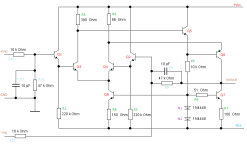
The new IPS-VAS can be controlled completely symmetrically in terms of voltage. It does not oscillate and only overdrives at loads (RL) below 3kOhm.
What is the input resistance of the Krill or the Stellema's Diamond-Outputstage, the buffer?
What is the input resistance of the Krill or the Stellema's Diamond-Outputstage, the buffer?

They will be thermally coupled at no more than ambiant temperature after they took their liberty
for an inherent big kaboom...
for an inherent big kaboom...
We obviously (can) find every hair in the soup
Anyone can do everything right, but doing everything wrong from the gut is real skill. What I'm trying to say is: that we know the recipe and the cooking times for the vegetables. And exactly this restrictive approach is totally boring.
Why did you abandon the L.Stellema project, the Tim? Just because everything converges at some point and at the end of the day you are once again left with the familiar basic circuit of a power amplifier, with the dimensions, the component values ... or were there other reasons?
Perhaps we can leave the VAS voltage amplifier (Self's diction) to one side - it really has been implemented very unconventionally, no question - and take care of the output stage, the voltage follower.
Why does my suggestion burn out because I didn't use 0.22Ohm emitter resistors, or because of the bootstrap capacitors ... ?

Q13 and Q14 are, of course, total nonsense without the limiting current sources as emitter resistors for the diamond driver or base series resistors for the end transistors (what do we want to call them, the snot?), unless they could have a stabilizing effect. Usually there is an ohmic resistance of perhaps 150 to 330 ohms at this point, i.e. from emitter Q9 to Q10.
The diamond limits and protects, which is of course not the case here - the only question is the following: will the snot stabilize thermally?
And where do we ceverly feed in, see schematic from post #155 and #158.
greetings,
HBt.
Psst.
@wahab
Do you have a constructive suggestion at hand that essentially makes do with the components of the Stellema suggestion?
Anyone can do everything right, but doing everything wrong from the gut is real skill. What I'm trying to say is: that we know the recipe and the cooking times for the vegetables. And exactly this restrictive approach is totally boring.
Why did you abandon the L.Stellema project, the Tim? Just because everything converges at some point and at the end of the day you are once again left with the familiar basic circuit of a power amplifier, with the dimensions, the component values ... or were there other reasons?
Perhaps we can leave the VAS voltage amplifier (Self's diction) to one side - it really has been implemented very unconventionally, no question - and take care of the output stage, the voltage follower.
Why does my suggestion burn out because I didn't use 0.22Ohm emitter resistors, or because of the bootstrap capacitors ... ?
Q13 and Q14 are, of course, total nonsense without the limiting current sources as emitter resistors for the diamond driver or base series resistors for the end transistors (what do we want to call them, the snot?), unless they could have a stabilizing effect. Usually there is an ohmic resistance of perhaps 150 to 330 ohms at this point, i.e. from emitter Q9 to Q10.
The diamond limits and protects, which is of course not the case here - the only question is the following: will the snot stabilize thermally?
And where do we ceverly feed in, see schematic from post #155 and #158.
greetings,
HBt.
Psst.
@wahab
Do you have a constructive suggestion at hand that essentially makes do with the components of the Stellema suggestion?
@hbtaudio
It is not possible to use sub par blocks to design a high performing arrangement.
If you limit the IPS gain and/or linearity and do the same with the VAS then whatever the OS this will change nothing
to the whole equation, and this design has limitations eveywhere, that s an exemple among others of how making bad use
of the component count, and adding components to compensate for those drawbacks is just irrationality.
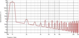
FTR a differential + VAS + EF3 use 14 transistors including 2 darlingtons for the OS, here the typical THD at 1KHz
and IMD for 400Hz/7kHz with 4/1 ratio, both graphs at 20V pk wich is 25W RMS.
Now try to do better with Stellema design and only 12 transistors + 2 power Darlingtons, small signal being BC 546/556
and BC141/161, darlingtons either BDV64/65 or TIP142/147, so all very cheap components, Sanken darlingtons would improve
the numbers but they are not cheap and some very good ones are even obsolete.
Greetings, and all the best.
Attachments

Your post leads to the interpretation that there is one single, ultimate topology that can achieve groundbreaking data that cannot be achieved with any other topology.
#
Please share with us readers of this thread this topology and the schematic you used to achieve the published simulation results.
Thanks wahab,
that's nice of you - I too know the topology, the components, and so on. However, I don't want to guess here and pay in advance, so to speak 😉.
I realized at a quick glance that your simulated THD and also the IM is less than / equal to 0.0001% under maximum load. In other words, in the reality to be specified, it is no better than 0.03% in the entire audio range and various load cases!
kindly,
HBt.
- Home
- Amplifiers
- Solid State
- high performance 25W PowerAmp