I don't understand you: you want audio, practical, i.e. audible results, but you want not practice audio, audible results. You can't categorize the different concepts in terms of sound because you don't practice them.
"My" "wisdom" comes from practical experience. I've been testing every little outlandish idea or opinion and every little hint in the field of "audio" for decades: call it "qualitative research": "science", not just electrical engineering knowledge;-)
There's my productive delivery;-)-:
I remind - see above: "hooooome-woooork"-)
Statically OK, can be moved in both directions - another ohmic resistance saved.
@cumbb, you're - the son of the gun; i know that - quite funny boy.
You just want to play and nothing else, are you an internet troll?
Why don't you send over a complete circuit that corresponds to your current state of research, that would be really great.
Quite a guy!
Let's end the topic of this "well thought-out" amplifier.
Very clear:
this schematic is junk!
Bye,
HBt.
Very clear:
this schematic is junk!
Bye,
HBt.

Any arguments for "this schematic has great potential and is worth modification or upgrade" ?this schematic is junk!
The input stage looks so very basic that this might be more a simplified concept schematic than a circuit ready to built.
Last edited:
There is a big question mark over all of this.
Dear Bernhard,
would you like to continue working on the L. Stellema design and make it a success?
25W with a minimum of components and really high performance - I'm really stumped, it seems to be a waste of time.
The call of temptation is so sweet, but the next rock is just waiting for the rapturous impact - 'wahab' has put this into poetic words so beautifully.
HBt.
Any arguments for "this schematic has great potential and is worth modification or upgrade" ?
The input stage looks so very basic that this might be more a simplified concept schematic than a circuit ready to built.
Dear Bernhard,
would you like to continue working on the L. Stellema design and make it a success?
25W with a minimum of components and really high performance - I'm really stumped, it seems to be a waste of time.
The call of temptation is so sweet, but the next rock is just waiting for the rapturous impact - 'wahab' has put this into poetic words so beautifully.
HBt.
Attachments
If we (want to) continue working on this topic together (and stay with the choice of transistors, the original, a possible output stage); the circuit will undergo some radical changes, I am completely convinced of this and have been from the beginning.
Every analysis needs a beginning and this is / was the article.
Every analysis needs a beginning and this is / was the article.
Do not give up;-)
I would first clarify what you want to prove here:
1. the audio suitability of the concept, circuit. Excluding the influence of the object, parts.
2. The further chance here should be to get to know push-pull to single ended!
3. and symmetrical (concept), but with asymmetrical parts (object; complementary transistors - result anticipated here)!
Because the goal is audio suitability, the only thing left to do is to build the thing and compare it with two or three other circuits by listening. And always diligently ensure differentiation and contrasting within the circuit, i.e. play around, create "accidents": Compare the thing with itself, for example by replacing the objects, the physical parts.
It's a endless task. But it is also the only way to work out a distinction between the concept (circuit) and the physical object (parts).
The method developing ("science") grows with the doing - and is certainly never complete, but will lead to differentiations and contrastings that enable orientation in the entire audio discourse - and essential, a prerequisite for "science" in general, the distinction: concept or object;-)
And since everyone has to make their own practical experiences, I will not anticipate the results here;-)
Let us call it "qualitative method" - to use a "scientific" term.
... because of university and so on - you know;-)
😉
So chewing through this rubbish is very challenging, more than just a test of patience, it borders on masochism.
The boat is bound to leak and later generations will try in vain to salvage the treasure of the Nibelungs before they have even found it.
A quick interjection as a picture attachment.
The boat is bound to leak and later generations will try in vain to salvage the treasure of the Nibelungs before they have even found it.
A quick interjection as a picture attachment.
Attachments
Siegfried bathed in the blood of the lindworm, but Hagen's spear ...
Assuming that our raft doesn't sink again immediately, now would be the time to follow L. Stellema's recommendations and give the IPS and the VAS (both sections are unfortunately voltage-boosting - and this has unpleasant consequences, as D. Self clearly points out in his printed work) an AC load in accordance with the T.I.M. doctrine.
Obediently, we must now torment the two-stage IPS-VAS combination so that its bandwidth and local gain are lowered in accordance with the legal text.
In the final step, we close the loop (i.e. counter-couple, call it nfb).
Now, at the latest, a light comes on - and Hagen already suspects the consequences of his actions.
Bye,
HBt.
Post script
Does anyone still want to get on board the experimental archiologists and hire them? "Moby Dick" is not at home in our local waters.
Nevertheless, I think it would be nice if we could at least make the 25WPA-hp suitable for inland waterways. It just doesn't feel good to slap the unfit stamp on the proposal. But if it has to be done, then at least with a heavy heart.
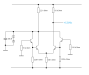
So Q5 and Q6 provide a current source drive for output transistors Q1 and Q2. The are not temp compensated and probably not matched. Only 0.6 volts across R7 which give a little less than 100mA and quite influenced by temp.. Tendency is to give higher bias at high temp which is not the right direction as Q1 gain goes up with temp
The only advantage I can see is a virtual constant drive source independent of output magnitude.

The only advantage I can see is a virtual constant drive source independent of output magnitude.
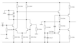
To improve that schematic and not morph it into a new amp, I would keep the function blocks, just pimp the stages going from left to right.
Start with the diff pair.
Maybe integrate the first with the second part to get rid of the two coupling caps.
Start with the diff pair.
Maybe integrate the first with the second part to get rid of the two coupling caps.
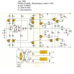
If one want to drive a symmetrical VAS then a symmetrical dual differental is the simplest way to have things
working correctly, here s SGS Ates take of Otala s ideas, 52dB OLG and 100kHz OL BW with 24.8db LG,
their AN was first pusblished in 1977 in a french review who recycled it in 1981 unchanged, notice the diamond buffer.
working correctly, here s SGS Ates take of Otala s ideas, 52dB OLG and 100kHz OL BW with 24.8db LG,
their AN was first pusblished in 1977 in a french review who recycled it in 1981 unchanged, notice the diamond buffer.
Attachments
In order to be able to assess the respective changes in sound, I recommend, even if you only set up and test one amplifier, i.e. mono, a pair of loudspeakers in their good stereo set-up (I have already written about this somewhere) to use. That way you can hear - what it's all about;-) Even in this arrangement, you can hear image size, depth, contour, cleanliness, clarity, tonality, the relationship between colours and contour, and much more.
... so that it doesn't just remain with hypothetical circuits on paper - or in simulation programs - without any reference to the audio task.
... so that it doesn't just remain with hypothetical circuits on paper - or in simulation programs - without any reference to the audio task.
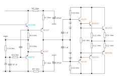
I can't make out a diamond or Mr. Diamond. What I can see is a normal balanced power amplifier with current limiting.(...) in a french review who recycled it in 1981 unchanged, notice the diamond buffer.
Perhaps there is no generally accepted definition for the circuit of a rhombus, the diamond!
Dear wahab,
I have now taken a closer look, and the circuit looks very familiar to me. And yes, you could buy exactly this circuit as a finished module in Germany for a long time. Not exactly, but slightly slimmed down and with a switch-on delay: OCL-950 from Monacor. This is now all decades in the past.
Many thanks for the original schematic, I remember the performance - without blame.
greetings,
HBt.
Symmetrical arrangement between the rails!What I can see is a normal balanced power amplifier with current limiting.
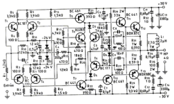
Would anyone like to go to the trouble of modeling the original power amplifier and running extensive simulations, as per my initial post #1 ?
Unfortunately, I'm tied up this weekend. Do we even have correct SPICE models of the BD203,4 & BD235,6 BJT's ? Who would like to contribute them ?
HBt.
Unfortunately, I'm tied up this weekend. Do we even have correct SPICE models of the BD203,4 & BD235,6 BJT's ? Who would like to contribute them ?
HBt.
Cast off Bernhard,To improve that schematic and not morph it into a new amp, I would keep the function blocks, just pimp the stages going from left to right.
Start with the diff pair.
Maybe integrate the first with the second part to get rid of the two coupling caps.
as a little pastime, to relax until your SuperDuper sees the light of day, I'm eagerly awaiting the release date.
Kind regards,
HBt.
🙂
- Home
- Amplifiers
- Solid State
- high performance 25W PowerAmp