Quite apart from hearing as an alarming and locating sense, yesterday I made the first simulation of the L. Stellema circuit (which I jokingly called "Tim" temporarily, because of the T.I.M. Spirit at that time). With the identical results that wahab has already made clear. The cause of the unwanted oscillation is also quickly identified, it is causally related to the doctrines (or design recipe) of the time. Simply put, the main problem is the chosen compensation method of the frequency response, of course the topology also looks very strange - and Ed's objections and displeasure are valid, but can be corrected.
Dear cumbb,
I would very much appreciate it if you would only be knowledgeable in the threads I have initiated (with complete and comprehensible sentence structure) and not, as usual (even in the German forums), simply throw in fragments to provoke.
To put it diplomatically and kindly,
HBt.
I would very much appreciate it if you would only be knowledgeable in the threads I have initiated (with complete and comprehensible sentence structure) and not, as usual (even in the German forums), simply throw in fragments to provoke.
To put it diplomatically and kindly,
HBt.

To be friendly to you once again:
Yes, a full range driver, completely electronically equalized -> can be a fabulous experience in almost every direction of the home listening experience -> many users on this board know this, for sure.
And I'm sure some of them can even answer the why questions adequately and physically correctly.
Cold coffee doesn't always have to be reheated!
"completely electronically equalized"
That's where the misconception lies: we can't get rid of the fullranges - or drivers and speakers in general - mechanical errors with electronic equalization.
Also, this idea only shows the less developed idea of signal and hearing: Audio.
So we should also be able to distinguish cold and hot;-)
That's where the misconception lies: we can't get rid of the fullranges - or drivers and speakers in general - mechanical errors with electronic equalization.
Also, this idea only shows the less developed idea of signal and hearing: Audio.
So we should also be able to distinguish cold and hot;-)
It really needs a lot of modification before it produces a clean sound. I once called Manger and told them what they had to do to the driver, after decades of experience the faults should be obvious.
That is interesting again:
Please send me all the information you have gathered on this sound transducer, as well as your design solutions, including and especially the material science.
I can be contacted by PM and will put you in touch with one or more contacts.
If you are interested in a university career at a German university, I will be happy to put you in touch, or will the inventors' circle be enough for you(?).
This is not a provocation on my part, but rather a fundamental interest of my faculty, indeed the entire university, in young, competent researchers.
Should I then train them, including lecturers, including you - in "Audio"-?!
You can see how much people are reluctant to have the simplest experiences;-)
The quality of education at universities has proven itself in the last 4 years: the majority is committing collective self-destruction. And the few who are educated enough and mature enough are defamed or even escorted out;-)
This is becoming increasingly not on topic, but I'd like to share. If you want to discuss further a thread split might be advisable.
Before looking at more often than not questionable hearing tests, it might be helpful to investigate whether your ear can differentiate between positive and negative deflection of hair cells in the first place. And thus absolute phase.
The answer to that is simple and straightforward: yes.
And if your brain is feed with a stimulus differentiating between positive and negative flanks
and nature found an evolutionary advantage in developing a staircase like stereocilia arrangement instead of a plain fence, with little ion channels which open on positive deflection,
only a fool would come to the conclusion that this information is not evaluated by the brain and is thus audible.
There have been rumors about audibility of absolute phase that I personally doubt.
Some googling produces links to AES papers, all behind a paywall.
Could you please give some link to substantiate this claim?
Before looking at more often than not questionable hearing tests, it might be helpful to investigate whether your ear can differentiate between positive and negative deflection of hair cells in the first place. And thus absolute phase.
The answer to that is simple and straightforward: yes.
And if your brain is feed with a stimulus differentiating between positive and negative flanks
and nature found an evolutionary advantage in developing a staircase like stereocilia arrangement instead of a plain fence, with little ion channels which open on positive deflection,
only a fool would come to the conclusion that this information is not evaluated by the brain and is thus audible.
https://www.sciencedirect.com/topics/neuroscience/stereociliumFrom: Fundamental Neuroscience (Fourth Edition), 2013
Axis of Polarity
The staircaselike variation in heights of stereocilia and the eccentric placement of the kinocilium at one edge of the bundle confer a morphological axis of polarity to the bundle. The positive direction is defined as toward the kinocilium or the tallest stereocilia; negative is toward the shortest stereocilia. This also describes the physiological axis of the bundle: a positive deflection of the stereocilia evokes an excitatory response. It increases the membrane conductance by triggering the opening of nonselective cation channels (transduction channels), allowing positively charged ions to flow into the cell and thereby depolarize the cell. At the bundle’s resting position, ∼10% of the transduction conductance is active. Thus, a negative deflection decreases the membrane conductance (closes channels open at rest) and hyperpolarizes the cell. This feature allows hair bundles to signal stimuli of either polarity.
https://biology.stackexchange.com/q...rsion-from-hair-cells-to-cochlear-nerve-cellsDuring a sine wave stimulus (a pure tone), the stereocilia of the hair cells deflect in one phase, and inflect on the other. One phase hence depolarizes the SGC, the other hyperpolarizes it. This generates a near-perfect representation of the sine wave input at low frequencies.
Road map
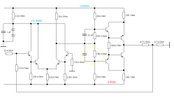
I think with these two quick sketches you can identify both the causal problems and the solution in plain sight - without having to name them explicitly.
Theoretically, nothing oscillates anymore, not even sporadically, and the bandwidth is greater than or equal to 1MHz.
Power must be supplied with constant, regulated +/-24Vdc. As has already been comprehensively established.
That would now be my first step in approaching the project, again completely freely, innocently and intuitively.
greetings,
HBt.
Attachments

A further thought, what if:
if we now add a suitable (push-pull output stage, not a diamond or a diamond after all?!) output stage to the rear, extract the resulting error and subtract, add or multiply it back to the front -> feedforward for /or intervene to correct the error.
We automatically rotate the phase again and at the same time isolate the stages from each other, but also take them back into the control loop.
🤔
After some sims i came to the conclusion that the more you want to improve the design the more it will gradually converge
either to a classical blameless or eventually to a symmetrical dual differential IPS, with both yielding either better perfs
or equal perfs but with a simpler and better working schematic, and with a lower component count in all cases.
The main culprit in this design is the VAS that AC load greatly the IPS and that also reduce its DC GNFB because of the DC
voltage attenuator at the VAS input, not counting that its topology is not compatible with an energic miller compensation
unless using huge caps that will increase greatly the distorsion.
The most elementary intelligence would aknowledge that trying to improve this design amount to trying to get a race horse
out of a stubborn donkey, and that that the design is just too flawed from the start to be worth the effort, but still, we can discuss about the causes of what is obviously a stratospheric failure from those Sydney aeronautics enginers.
Oh dear - that was actually clear from the start. The deeper we question, the more we end up with Self's blameless approach, economical, simple and elegant, with really excellent results.
I'm very sorry, after all I dug up the article by accident. Hopefully you won't find your study of L. Stellema's circuit diagram a waste of time now.
I'm very sorry, after all I dug up the article by accident. Hopefully you won't find your study of L. Stellema's circuit diagram a waste of time now.
hbtaudio - No need to apologize. L. Stellema's circuit was an interesting look back at history. I learned that the diamond buffer was named after its inventor. 🙂
Researchers advance the state-of-the-art by starting from the state-of-the-art. Put your efforts into improving those amplifiers. This board has several state-of-the-art designs.
Ed
Researchers advance the state-of-the-art by starting from the state-of-the-art. Put your efforts into improving those amplifiers. This board has several state-of-the-art designs.
Ed
(...) but still, we can discuss about the causes of what is obviously a stratospheric failure from those Sydney aeronautics enginers.
Yes wahab,
I think we all owe it /this to the circuit, the article and a summary of this thread.
#
If you would like to, you can still invest in a test assembly - after all, diy is a matter of enjoying DIY and experimenting. Good cooks don't get annoyed if their latest recipe designs or Hildegard von Bingens survival cookies don't taste particularly good.
In the spirit of an experimental archaeologist, I'm not going to give up just yet. You're not upset about that, are you?
Starting from absolutely constant operating voltages of +/-24Vdc, I'll take another static look at the potentials and the load on the IPS (Q1 to Q4) by the VAS (Q5 to Q8).
And if there is no reason not to take a further step, I look at the dynamic case at steady state.
I am not yet ready to give up, well aware of all the adversities of the original and listening to the cries of warning
R1 now 13k6Ohm for better balacing.
What kind of garbage? But I don't want it to be true.
🙄
R1
absolutely has to approach zero, otherwise the oscillation will be there - and as we already know, we can't compensate sensibly.
R12
must be greater than R11, otherwise an almost symmetrical modulation between the rails is impossible.
We can actually save ourself the test setup. I wonder whether the original ever really worked reliably. Let's see if I invest some more time, one obviously have to be very tough for this circuit.
Pretty cruel.
Attachments
Last edited:
Yes wahab,
I think we all owe it /this to the circuit, the article and a summary of this thread.
#
If you would like to, you can still invest in a test assembly - after all, diy is a matter of enjoying DIY and experimenting. Good cooks don't get annoyed if their latest recipe designs or Hildegard von Bingens survival cookies don't taste particularly good.
Curiously i made all my scolarship and is still living 200 km south east of Rupertsberg in what was part of Hildegard s land
at the time, just next to the Rhine, indeed this design is some kind of Lorelei whose charming voice will lure you crashing
on her rock, but fortunately we have simulators to test those deep, and muddy, waters before engaging in a build that would
end as yet another big disappointement.
There s really no miracles to hope for, lot of catastrophic, or at best mediocre, designs are still revered as the end of all,
after all those dubbious amps work well enough that they are still considered as relevant while all they demonstrate
is not that they are good but that NFB work so well that it can often compensate for most of the blunders of a hasardous design.
Methodologically, I would take a different approach: build the thing - it's not complex - and listen music. And then the character would be shown - whether it's worth investing any work at all in terms of: visible line at the input vs. visible line at the output;-)
What I can already predict is that this pre circuit has the higher sound potential than any highly praised and paid ML or Accuphase or whatever pre crcuit;-)
... but it is still not an audio circuit)-;
What I can already predict is that this pre circuit has the higher sound potential than any highly praised and paid ML or Accuphase or whatever pre crcuit;-)
... but it is still not an audio circuit)-;
The miracle of negative feedback, I know.(...) is not that they are good but that NFB work so well that it can often compensate for most of the blunders of a hasardous design.
My dear cumbb!
As so often, you speak in riddles, or should it be a Zen master's koan (?).
Please deliver something productive,
something more than just an appeal for a practical experiment - "auch wenn dieser (insbesondere bei mir) offene Türen einrennt". Breaking down open doors.
Where do you get your wisdom from?
HBt.
- Home
- Amplifiers
- Solid State
- high performance 25W PowerAmp