Dear wahab!
I would really appreciate it if you could provide a concrete suggestion - from your pen, max 25W.
In the spirit of this thread.
HBt.
I would really appreciate it if you could provide a concrete suggestion - from your pen, max 25W.
In the spirit of this thread.
HBt.
Your post leads to the interpretation that there is one single, ultimate topology that can achieve groundbreaking data that cannot be achieved with any other topology.
#
Please share with us readers of this thread this topology and the schematic you used to achieve the published simulation results.
Thanks wahab,
that's nice of you - I too know the topology, the components, and so on. However, I don't want to guess here and pay in advance, so to speak 😉.
I realized at a quick glance that your simulated THD and also the IM is less than / equal to 0.0001% under maximum load. In other words, in the reality to be specified, it is no better than 0.03% in the entire audio range and various load cases!
kindly,
HBt.
That s no more than the classical blameless refined without some limitations that are present in Self s schematic,
i stated the transistors references.
On the reality of the numbers i m sure of the results as i use only well modeled transistors because not only there s
more parameters but they also produce much lower numbers than some devices models that are vastly used by here
but that i discarded because of their apparently too good results, this can be checked on basic schematics that rely mainly
on the components linearity.
You ll notice FI that BDV64/65 and their equivalent TIP42/147 produce atrocious numbers in basic schematics,
and while BC141/161 and BC546/556 are average all are quite inferior to say 2SA1943/2SC5200 + 2SA1837/2SC4793
and other 2SA970/2SC2240, 2A992/2SC1845 or 2SA1381/2SC3503.
As to provide the exact schematics i would have done it 20 years ago eventually but the times have changed,
sites like DIY Audio are browsed by people in search of well designed schematics for implementing commercial offerings
mainly through chinese kits and the likes, so it s out of the question to offer free work to people that are driven by theft
for financial advantages.
Last edited:
Ok, that is a standard circuit that has exactly nothing in common with the initial schematic.random commercial template
Dear wahab!
I would really appreciate it if you could provide a concrete suggestion - from your pen, max 25W.
In the spirit of this thread.
HBt.
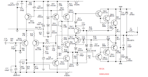
D. Self s Blameless schematic is this one, that s quite different from the Cambridge audio, he specify his improvement points,
this is a good basis that can be enhanced in some details and this kind of topology is one of the most efficient when
it comes to the perfs/component count ratio.
Attachments
Last edited:
This was clear to everyone from the outset, but “Blameless-Amp” is the clear term for the recipe (i.e. the sizing instructions) recommended by Douglas Self. No more and no less, because the topology is much older - as we all know. You have named and labeled semiconductors, yes. But you have not (yet) specified, identified the limitations of Self's diction ...That s no more than the classical blameless refined without some limitations that are present in Self s schematic,
i stated the transistors references.
Agreed, consensus - I handle it the same way.On the reality of the numbers i m sure of the results as i use only well modeled transistors because not only there s
more parameters but they also produce much lower numbers than some devices models that are vastly used by here
but that i discarded because of their apparently too good results, this can be checked on basic schematics that rely mainly
on the components linearity.
You ll notice FI that BDV64/65 and their equivalent TIP42/147 produce atrocious numbers in basic schematics,
and while BC141/161 and BC546/556 are average all are quite inferior to say 2SA1943/2SC5200 + 2SA1837/2SC4793
and other 2SA970/2SC2240, 2A992/2SC1845 or 2SA1381/2SC3503.
Consensus!
As to provide the exact schematics i would have done it 20 years ago eventually but the times have changed,
sites like DIY Audio are browsed by people in search of well designed schematics for implementing commercial offerings
mainly through chinese kits and the likes, so it s out of the question to offer free work to people that are driven by theft
for financial advantages.
Your last paragraph could be seen as an evasion - as much as I agree with you, but ...
I'm just interested in your recipe, the preparation and your finished dish - just like a chef pays tribute to another chef, nothing else.
HBt.
You have recognized this correctly Bernard, except that both perform the same task with more or less bravura as an AF power amplifier.Ok, that is a standard circuit that has exactly nothing in common with the initial schematic.
D. Self s Blameless schematic is this one, that s quite different from the Cambridge audio, he specify his improvement points,
this is a good basis that can be enhanced in some details and this kind of topology is one of the most efficient when
it comes to the perfs/component count ratio.
I say that always and everywhere 😒.
#153 plus krill
fits; only the Stellema output stage would have to have at least twice the input impedance, ergo bootstrap - if I'm looking at it correctly?!
Or are you alluding to the TIM doctrine?
fits; only the Stellema output stage would have to have at least twice the input impedance, ergo bootstrap - if I'm looking at it correctly?!
Or are you alluding to the TIM doctrine?
@Bernard,
I am concerned with the question of what we rate as bad and what we rate as good (with reasons).
Stellema's suggestion has been rightly criticized and censored, yet it works - somehow. No one who has spoken here so far has recommended a replica. The challenge is to design a similar circuit with fewer shortcomings - otherwise I'm completely on wahab's and Ed's side.
regards,
HBt.
This would be my first modification, two 2.7V Z-diodes. 2SC2240-GR or BL and BC550C. Separate power supply units are a matter of course. The unloaded potential of +12V is pulled close to zero by the peculiar VAS.
But I don't want to stick to the original either, not by any means.
Just a reminder!
We have to accept that circuits or application notes can simply be stolen and used commercially. Especially by the Asian kit faction. However, we are in the DIY sector and do not have to hide any secrets. DIYers want to learn from each other and as a professional you can calmly be helpful.(...) times have changed,
sites like DIY Audio are browsed by people in search of well designed schematics for implementing commercial offerings
mainly through chinese kits and the likes, so it s out of the question to offer free work to people that are driven by theft
for financial advantages.
That is my point of view as an amateur.
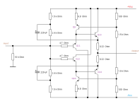
Tim's outputstage - the Diamond Buffer
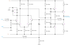
This is a very quick modification, without any simulation. I think it's better to look at this and the first stage on the actual test setup.
I am convinced that we can create a functional Stellema, the Tim.
Some key points must be finalized in the test setup.
Have fun and enjoy it 🙂.
This is a very quick modification, without any simulation. I think it's better to look at this and the first stage on the actual test setup.
I am convinced that we can create a functional Stellema, the Tim.
Some key points must be finalized in the test setup.
Have fun and enjoy it 🙂.
Attachments
Initial Summary
Ed's points of criticism were
1) the circuit should be operated with a stabilized power supply unit
2) the dielectric strength of the coupling capacitors is not sufficient
3) the THD achieved is solely due to the degree of coupling-factor, the negative feedback!
wahab's points of criticism were
1) the dielectric strength of the semiconductors used is not sufficient
2) coupling capacitors are unforgivable
3) the entire circuit is a inverting one
4) without frequency compensation the circuit oscillates
5) strange VAS-Struktur
6) no Douglas Self's blameless design!
We then buried the original design, but someone didn't give up and exhumed the corpse - Dr. Frankenstein got to work.
His creature is now waiting to be electrified
😱.
Last edited:
There is no harm in electrifying it - just don’t expect world class performance. It will be better than the 2000 watt amplifier built around a single TIP41 and running of a 12 volt wall wart - the one in that stupid you tube video floating around here somewhere.
No, of course I don't do that.There is no harm in electrifying it - just don’t expect world class performance.
<0.03% THD in the 30Hz to 15kHz range, between 500mW and 10W, is perfectly fine for me personally. Better than this scenario is also very welcome.
How do you define world's best (class) performance?
regards,
HBt.
- Home
- Amplifiers
- Solid State
- high performance 25W PowerAmp