I finally replaced the irs21844 tried to aply the less heat posible/
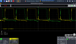
i got 40 hz in the gate as you will see in the pics this 40 hz are in the negative rail
in the positive rail i did not found the signal see the picture please i saw 80 hz very weak signal
the driver boar is not heat anymore
but i do not know if the fets must be installed for the board to start oscilation.


You won't get high-side drive without supplying voltage across the VS and VB. A 9v battery will serve as a supply.
do you recommend put 9 volts between VS an VB? or can i install one good tested original fet per rail ? this amp has only one bank per rail
It's more risky to test with FETs in and full rail voltage. Either using the 9v battery or using lower rail voltage is less risky.
Connect a load across the speaker terminals if you don't see the high-side drive after connecting the 9v battery if that's what you decide to do.
Connect a load across the speaker terminals if you don't see the high-side drive after connecting the 9v battery if that's what you decide to do.
Perry i have some time to continue with this amp iam ready to Apply 9 volts dc between Vb and Vs, i have a question, looking at the schematic, in VB, i Will conect +9volts?. And VS goes to ground?
That Will be 18 volts?
+9volts. Down to 0v(ground) Will be 9v and 0 volts to -9 volts Will be another 9 volts.
I apologize if i did not understand
+9volts. Down to 0v(ground) Will be 9v and 0 volts to -9 volts Will be another 9 volts.
I apologize if i did not understand
The battery has only two terminals.
You used 'ground' in your description. The battery has no ground terminal so I was trying to clarify.
You used 'ground' in your description. The battery has no ground terminal so I was trying to clarify.
Thank you, may be, it seemed like a fool question, but i wanted to be shure i understood correctly.
Was only to confirm because you mentioned only one battery , not two.
9v + VB
0v - VS
I do not want to damage the IC.
Was only to confirm because you mentioned only one battery , not two.
9v + VB
0v - VS
I do not want to damage the IC.
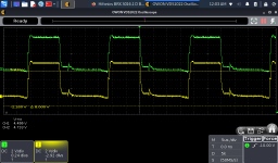
Apparently the PS section has still problems, i post a picture please tell me if the signals looks fine to you
is not perfect square and have some weird peaks. (the picture is with no fets in the audio section)
the PS driver transistors originally installed was A1013 and i installed a 1220, could this be the cause, the PS fets irf3205 (for testing) got warm after a few minutes without load.
is not perfect square and have some weird peaks. (the picture is with no fets in the audio section)
the PS driver transistors originally installed was A1013 and i installed a 1220, could this be the cause, the PS fets irf3205 (for testing) got warm after a few minutes without load.
Attachments
Try connecting the scope probe's ground clip to the source leg of the PS FETs. Absolutely do NOT let the clip short to the middle leg of the FET.
I apologize,is source pin you are correct, the drain is the Middle pin, i connected ground clip to side pin 3rd from left to right
The signal Looks noisy i think
The signal Looks noisy i think
Last edited:
It is noisy but it may not be a problem.
Where does the signal become noisy? At the driver IC? At the base of the drivers? Emitter of the drivers?
Where does the signal become noisy? At the driver IC? At the base of the drivers? Emitter of the drivers?

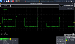
I don't know what a 220 is but the transistor appears to be working as it should. Much of the noise is due to the gate resistors.
What are the gate resistors?
Are the PS FETs the same as the originals?
What are they?
What are the gate resistors?
Are the PS FETs the same as the originals?
What are they?
i replaced 2sA1013 With 2sA1220, i have used A1220 in another amps as a replacement and worked fine, but the other amps has bigger gate resistances like 47 ohms
The resistor in gates i think are 22 ohms i Will confirm in a moment
The original fets were irfp064n, i did not have in hand and for the repairing process im using irf3205, almost identical except for the case and the current capacity.
The resistor in gates i think are 22 ohms i Will confirm in a moment
The original fets were irfp064n, i did not have in hand and for the repairing process im using irf3205, almost identical except for the case and the current capacity.
If you have the BD139 and BD140, it may give you a slightly cleaner signal. It's a slower transistor so the noise 'may' be reduced with the 139/140.
- Home
- General Interest
- Car Audio
- Hifonics BRX 3016.1 D Brutus