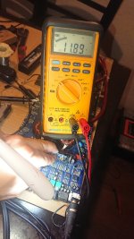
117.8 volts dc in pin 7 grounded in negative rail at first check it was 11.9 but the attenuator 10x switch in the scope was active
Last edited:

I measured fron pin 1 to 7. Negative rail referenced to ground mmeter
Pin 1 = 9.1 volts
Pin 2 = 11.61 volts
Pin 3 = 0 volts.
Pin 4=. 2.49 volts
Pin 5. = 0. volts
Pin 6. = 0 volts
Pin 7. = 11.89 volts
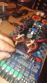
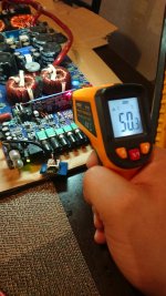
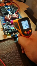
The IRS disipator is hot and with no fets installed I post pictures from disipator temp and tem from another points in the board 11 °C difference between disipator and board
Pin 1 = 9.1 volts
Pin 2 = 11.61 volts
Pin 3 = 0 volts.
Pin 4=. 2.49 volts
Pin 5. = 0. volts
Pin 6. = 0 volts
Pin 7. = 11.89 volts
The IRS disipator is hot and with no fets installed I post pictures from disipator temp and tem from another points in the board 11 °C difference between disipator and board
Attachments
If you connect a 10k resistor across pins 1 and 2 of the TL072, how does the voltage on pin 1 of the driver IC change.
Pin 2 shouldn't be above 5v. It's either being driven high by an external voltage or the IC is defective. Lift the terminal and re-check the voltage on the pad and on the lifted terminal.
Pin 2 shouldn't be above 5v. It's either being driven high by an external voltage or the IC is defective. Lift the terminal and re-check the voltage on the pad and on the lifted terminal.
I checked voltage in pin 2 desoldered from the pad I got 321milivolts in pad. And 10.78.in pin 2 the voltage stays in the pin this vales was taken with no signal of audio.
Looking a the results, The IC seems to be bad, I understand from your last post
Do i understand correct?
With this results, is relevant to bridge pin 1 to pin 2 of the tl072 with 10k resistance??
Looking a the results, The IC seems to be bad, I understand from your last post
Do i understand correct?
With this results, is relevant to bridge pin 1 to pin 2 of the tl072 with 10k resistance??
Look at the diagram. From what it shows, the SD terminal is pulled up to 5v internally. From the notes I have, that terminal commonly pulls up to about 4.3v.
If you install the resistor, you can check the operation of the TL072, the LM211 and check the input signal to the 21844.
If you install the resistor, you can check the operation of the TL072, the LM211 and check the input signal to the 21844.
Attachments
Ok thank you, I can see, this voltage of 10 volts in pin 2 is out of range, I will replace the Irs21844 I, m 99 % certain is bad.
Perry what do you think? I was thinking replace the Irs21844, with the switching board mounted on the mother board
Do you think is posible or is more conveniente to unmount the switchIng board?
Do you think is posible or is more conveniente to unmount the switchIng board?
I replaced driver board components with the driver board in the amp unless there were components in the way. If you can get the heatsink off of the IC without removing the driver board, I'd try to replace it in place.
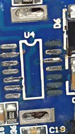
Tape off the other components with Kapton tape, apply additional solder to both rows of pins and heating both rows of pins, alternately, you should be able to slide the IC off of the end of the board.
Tape off the other components with Kapton tape, apply additional solder to both rows of pins and heating both rows of pins, alternately, you should be able to slide the IC off of the end of the board.
The pads are sensitive to a combination of heat and the time that the heat is applied.
A 1/8" (3mm) length of ChipQuik on each side using about 400F and plenty of the flux shipped with ChipQuik will reduce the risk to the board. If you have any junk boards with SMD components, you can practice removing and reinstalling the same ICs to see what it takes to remove the ICs without damaging the pads. It's mostly the unused pads (with no way to sink the heat away) that get damaged. Board quality also affects the risk of damage. If you have the repair tutorial, read Tech Tips 5, item #20.
There are only the VS, HO and VB that are used on that side.
- Home
- General Interest
- Car Audio
- Hifonics BRX 3016.1 D Brutus