My mistake. Wrong thread.
Do you get the 40Hz signal at the input to the driver IC (21844)?
At the output of the LM211?
Do you get the 40Hz signal at the input to the driver IC (21844)?
At the output of the LM211?
Last edited:
just for information i got signal of 40 hz in the first 4558d finally i just incresed to 1.3 volts the signal an i got it.
signal was not big enough.
and yes i got signal in pin 1 of the TL072, but no signal at the output of the lm211 in pin 2 and pin six of LM211 i got 40hz signal
lm211
pin 1= 5volts
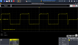
pin 2 40 hz square signal
pin3 0 volts
pin 4 5 volts
pin 5 5 volts
pin 6 40hz square signal
pin 7 0 volts
pin 8 0volts
signal was not big enough.
and yes i got signal in pin 1 of the TL072, but no signal at the output of the lm211 in pin 2 and pin six of LM211 i got 40hz signal
lm211
pin 1= 5volts
pin 2 40 hz square signal
pin3 0 volts
pin 4 5 volts
pin 5 5 volts
pin 6 40hz square signal
pin 7 0 volts
pin 8 0volts
Attachments
yes i was wrong invrted pins 5 to 8
lm211
pin 1= 5volts
pin 2 40 hz square signal
pin3 0 volts
pin 4 5 volts
pin 5 0 volts
pin 6 0 volts
pin 7 40hz square signal
pin 8 5volts
lm211
pin 1= 5volts
pin 2 40 hz square signal
pin3 0 volts
pin 4 5 volts
pin 5 0 volts
pin 6 0 volts
pin 7 40hz square signal
pin 8 5volts
I want to check pin one in irs21844 but is a bit difficult to acces the pins with the disipator installed.
am I correct? In pin one I got to see square signal coming from pin 7 of the lm211?
am I correct? In pin one I got to see square signal coming from pin 7 of the lm211?
The signal will be referenced to the negative rail (scope ground for that scope). You can get the signal on the collector of the level-shifting transistor, Q7.
Yes. It should be a square wave of about 10v amplitude.
Yes. It should be a square wave of about 10v amplitude.
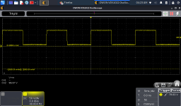
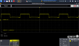
I got 40hz in pin I think is colector q7. Posted pictures
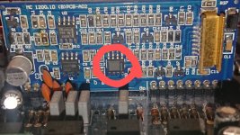
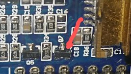
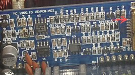
I got 40hz square wave in the pin I think is number 1 of the IRS chip
Another test you can sugest before I change the IRS chip? I measure the value of the cap CL 1 is 10.7 uF
Red arrows showing pins
I got 40hz square wave in the pin I think is number 1 of the IRS chip
Another test you can sugest before I change the IRS chip? I measure the value of the cap CL 1 is 10.7 uF
Red arrows showing pins
Attachments
I put the black prob in the negative rail the negative rail is conected to the IRS chip disipator I recheck an is conected as you said
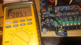
The voltage of 113 volts sound not right? Is about 27 volts ground
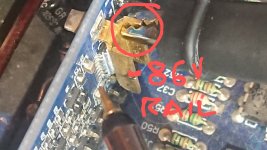
-86 volts to ground. And the voltage measured is 113 between negative rail and pin 2 I believe scope ground is conected to - 86 rail
I posted some images ground of volt meter is conected to rails ground
The voltage of 113 volts sound not right? Is about 27 volts ground
-86 volts to ground. And the voltage measured is 113 between negative rail and pin 2 I believe scope ground is conected to - 86 rail
I posted some images ground of volt meter is conected to rails ground
Attachments
Place the black probe either on the output leg of the negative rectifier or on the shunt resistors.
Ok I will do it, but is zero resistance between the shunt resistors and the disipator, I conected the scope ground in the disipator Because is easier for distance of the ground cable of the scope is like 12 cm length.
I comment the results
I comment the results
- Home
- General Interest
- Car Audio
- Hifonics BRX 3016.1 D Brutus