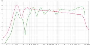
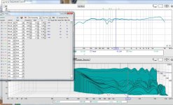
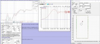
So here come the measurements! These are all taken 60cm away, on-axis, 88cm from the floor (mic height exactly between the two drivers which incidentally is also the listening height). The full-range one is taken with 350Hz Harsch XO (4th order BW on woofer, Bessel with 1,6ms delay on fullrange).
What I can immidiately see is no phase shift on crossover frequency! I uploaded all measurements to my dropbox, and would appreciate if someone with a bit more experience with REW could take a peek. One of the things I'm wondering is the 800Hz bump on the speakers. From what I've simulated with Edge, it seems this is probably caused by the baffle step. Still, didn't expect it to be that steep.
https://www.dropbox.com/s/5ggxg0hssvuuo38/measurements.zip?dl=0
Agree 800Hz bump looks a bit too much, wonder if its edges from SLS 12 that The Edge is not aware of when running 10F simulation, also some laptops can have DSP running in background to enhance sound from laptops small speakers that will make weird measurements and have to be disabled.
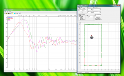
Attach below how mine 10F and 10inch woofer with Jriver DSP ended up at 50 cm distance 355Hz LR8 linear phase XO, in first plot your left speaker is overlaid with mine final curve, window setting is FDW 1/6 width in octaves. Placing ones ears in same 50 cm position as microphone and at same time routing both left and right signal to that mono speaker reveal crazy high sound quality and pleasure, but of course as one back out into room quality decrease some.
Have best end of the day enjoying brandy and Finish music 🙂
Attachments
Last edited:
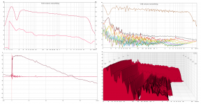
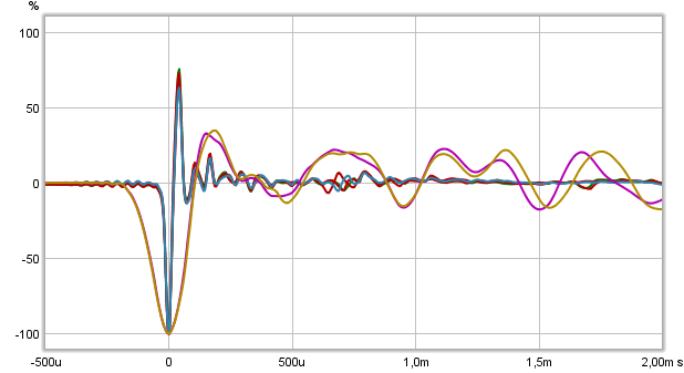
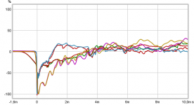
That dip at 800 Hz is there in the early signals. Looking at your IR you can see the first bigger disruption at ~3.45 ms, so your gating could be set just before that and be pretty much clear of reflections. The dip is already there at this point though, and could come from edge diffraction. But it could also be something else (the back chamber).
Do you have means to make an impulse reading of your 10F in the enclosure? REW can do that with a few wiring tricks and a known resistor. That would tell us if it's from within the box or something else from the outside.
Do you have means to make an impulse reading of your 10F in the enclosure? REW can do that with a few wiring tricks and a known resistor. That would tell us if it's from within the box or something else from the outside.
Don't do that just yet, I can EQ out the ripple, but that would only work if it's consistent over a wider area. Meaning the off axis would have to have the same dip to make EQ work.
So we'd have to know if the dip is consistent off axis before using this much EQ.
Here's a quick example:

EQ = off...

EQ is on...
I deliberately show the waterfall to see what it does for the early signal. This waterfall is limited to 3ms, it shows the dip is already there before the first obvious reflection takes place.
Sorry to set the EQ back to Generic, it's easier for me to predict it's outcome and I only wanted to see if we could clear up that dip. The very high Q PEQ settings won't work if the dip is changing shape off axis. We need to see on axis and every 5 degree step out to ~25 degree to see what is happening. It could also change if the mic is moved further back. Any dip that changes once we move further away (with the mic) we won't be able to "EQ" out either.
So we'd have to know if the dip is consistent off axis before using this much EQ.
Here's a quick example:
EQ = off...
EQ is on...
I deliberately show the waterfall to see what it does for the early signal. This waterfall is limited to 3ms, it shows the dip is already there before the first obvious reflection takes place.
Sorry to set the EQ back to Generic, it's easier for me to predict it's outcome and I only wanted to see if we could clear up that dip. The very high Q PEQ settings won't work if the dip is changing shape off axis. We need to see on axis and every 5 degree step out to ~25 degree to see what is happening. It could also change if the mic is moved further back. Any dip that changes once we move further away (with the mic) we won't be able to "EQ" out either.
Attachments
Last edited:
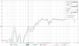
One more note, both of your HF measurements have their initial peak downwards which means they are wired out of phase...
wesayso think it looks like all 6 measurements perform negative polarity from somewhere in chain.

Attachments

Last edited:
That's very strange. I just checked with the battery test, leads are correct on the amplifier end (connecting 1,5V battery to + lead makes the cone move forward).
About the measurements, I'll redo them tomorrow or on thursday. Now it's getting too late for noisy stuff 🙂
About the measurements, I'll redo them tomorrow or on thursday. Now it's getting too late for noisy stuff 🙂
Yes, indeed you are right. I only looked at the HF ones, they show very similar behaviour. Probably the baffle/nearby woofer causing the dip due to diffraction etc.
That's very strange. I just checked with the battery test, leads are correct on the amplifier end (connecting 1,5V battery to + lead makes the cone move forward).
About the measurements, I'll redo them tomorrow or on thursday. Now it's getting too late for noisy stuff 🙂
Get some at this same distance, at least a few a bit further out and at the near distance a few off axis ones. We'll find what's causing the dip, or at least see if we can EQ it out.
By the way, in the EQ plots I used no gating for the FR and set it to a 6 cycle frequency dependent window. Just for your information.
I'm guessing I'll be quite known/infamous for using that 5 or 6 FDW by now 😀.
Last edited:
Have four brands of microphones myself 2x analog and 2x USB and can report that UMIK-1 always flip polarity compared to three others.
Have four brands of microphones myself 2x analog and 2x USB and can report that UMIK-1 always flip polarity compared to three others.
Well, there you probably have the cultrip. I use UMIK-1 which came bundled with the MiniDSP 2x4HD.
Well, there you probably have the cultrip. I use UMIK-1 which came bundled with the MiniDSP 2x4HD.
Think we nailed it then, into Preferences/Soundcard/Input-Options you can tick "Invert" and all future measurements then go positive.
.....I'm guessing I'll be quite known/infamous for using that 5 or 6 FDW by now 😀.
Indeed and thanks sharing knowhow.
Looking further up the FR scale and EQ-ing a bit more I'd have to say: I love that 10F driver! Lets wait and see some more data before we commit to any real EQ. You've got to love that clean IR though. Marvellous clean driver.
Last edited:
I love that 10F driver! Lets wait and see some more data before we commit to any real EQ. You've got to love that clean IR though. Marvellous clean driver.
I can wholeheartedly second this. It sounds excellent.
By the way, don't spend too much time EQing for me. I upgrade my MiniDSP 2x4HD to DDRC-24 with Dirac Live processing to have to do the room corrections simultaneously with crossovers. It does room corrections with target curves. Read a bit about room correction on linux, and it all went very much over my area of comfort. Figured that I'll get to the same result much easier without reinventing the wheel 😀
However, I'm still keen on getting my response as flat as possible before DSP, so I'll dig on to that 800Hz notch when I get some spare time.
Last edited:
I'm just fooling around... no worries. I hope the Dirac processing is worth it, it would be best to solve as much as you can with passive means. However this dip isn't a reflection gone bad. It's something shared by both channels though. they do pretty much the same thing. So it could very well be the shape/size of the enclosure.

If you ever have the means... an impedance plot tells way more than most give it credit for. One resistor and a few specific wires and you're ready to roll. It would mean you'd see if there's anything from within the enclosure causing any harm.
A fun exercise is to look up measurements from people that include an impedance plot. Look closely at blips on the impedance plot and check out the FR at that frequency. There's bound to be something there (unless overly smoothed). If such things can be avoided by knowing your damping scheme is working (by checking the impedance curve) you'd have one less thing to worry about.
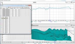
Attachments
Last edited:
In the mean time listen with these 2 EQ settings applied to both left and right HF driver...
(see attachment, you can import it in the EQ window in REW)
Listen to it and see if it's different/hopefully better. It might not work out but it can't hurt to try. It would depend on the dip being there at the listening spot.
Else you're going to have to listen at 60 cm 😀.
(see attachment, you can import it in the EQ window in REW)
Listen to it and see if it's different/hopefully better. It might not work out but it can't hurt to try. It would depend on the dip being there at the listening spot.
Else you're going to have to listen at 60 cm 😀.
Attachments
Checked the baffle again with Edge, and found a familiar pattern there. Disregard the freq. area, Edge can only simulate 1m height as my enclosure 1,2m tall. This surely makes me regret my decision to flip the drivers over when I was building, would have been so much easier just let them be as I originally intended. It's always a world of tradeoffs, because this way got me the 10F to be on ear level with my listening chair. Oh well, I just need DSP to save me now.
Attachments
Last edited:
Do look at the scale of the dips in Edge though. It looks worse than it is. Plus minus 2 dB is the deviation. Your dip at 850 Hz is 5 dB at the measured distance.
Here a rough example with your baffle in 1,2 meter height and changed diameter to same as middle of surround for 10F. Green is microphone distance at 100 meter as yours had where purple is at 3 meter and red is 0,6 meter hitting 800Hz dip. Unfortunate it changes with distance, same change will happen if microphone is placed 50 cm right to baffle verse 50 left to baffle, where if driver had been in center line of baffle same distance right or left produce same response. To change X and Y axis in The Edge place mouse at one end or the other end of scale and mouse turns into a arrow that will guide you, and place it in the middle will give a double arrow to adjust offset of plot.
Attachments
Last edited:
- Status
- Not open for further replies.
- Home
- Loudspeakers
- Full Range
- Hi-End Full-Range project