Here's three REW sweeps at the listening position of my room with the modded Wharfedale Diamond 6Rs taken with UMIK-1. Interpreting the graphs and getting used to REW & rephase is the biggest challenge I have in this project, so I'd appreciate all help 🙂
I've been tinkering with my Raspberry Pi player and got BruteFIR to run on it. Tried my wings at importing a REW generated room correction filter to rephase, since nowadays it can output the BruteFIR supported 64 bit IEEE-754 format, but had no idea how to get the file formats to match. It seems rephase can only import a file with .rephase extension?
Also been having problems with the audio center stability. Sometimes, it doesn't output sound at all and requires multiple reboots to get it functional. I think it might be insufficient power supplies fault, since my 5V 2,5A transformer gets extremely hot running it. Ordered a 5V 6A SMPS from eBay, it should help a bit.
Last edited:
A day off from university today, so I made the best of it. It's a beautiful snowfall outside and I'm inside banging on my speakers like crazy 

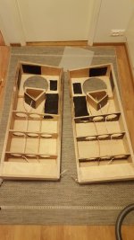
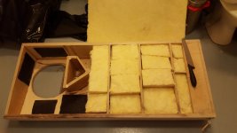
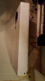
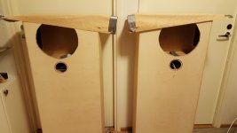
I was worried that the enclosures top part will act a bit like a BR enclosure to the bottom part, so I cut a bit of extra wood away that connected the FR enclosure to the side. I put a small wooden brace on both side which isn't showed in this picture yet. Also heated the bitumen pads up and compressed them against the ply. They aren't going to come off any time soon.

Since these are sealed enclosures, I'm using fiberglass for dampening. Peerless application note was 70l 65% fill, but I think I have more akin to 70% of the enclosure filled. The rest can be easily filled with polyfill if deemed necessary. It's very very lightly packed, enough that the fiberglass panels stay at place but not enough to compress them.

Here's everything sealed up. The back is screwed & glued on, so no need for clamps.
I was worried that the enclosures top part will act a bit like a BR enclosure to the bottom part, so I cut a bit of extra wood away that connected the FR enclosure to the side. I put a small wooden brace on both side which isn't showed in this picture yet. Also heated the bitumen pads up and compressed them against the ply. They aren't going to come off any time soon.
Since these are sealed enclosures, I'm using fiberglass for dampening. Peerless application note was 70l 65% fill, but I think I have more akin to 70% of the enclosure filled. The rest can be easily filled with polyfill if deemed necessary. It's very very lightly packed, enough that the fiberglass panels stay at place but not enough to compress them.
Here's everything sealed up. The back is screwed & glued on, so no need for clamps.
Attachments
Last edited:
Another progress update. This thread is like a blog, just me posting 🙂
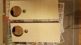
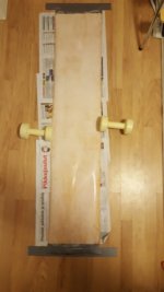
After pondering for quite some time how I'll treat the baffle edges and the sides/top, I decided to veneer them. It seems the easiest way of obtaining a good finish in this case. So, I went and bought some birds eye maple veneer from a local carpenter. Due to the shape of the edges I can't use clamps to glue the veneer, so I must try the ironing method. It goes like this:


Grab some PVAC or PVA glue (white glue) and water it down a bit. When it's runny and easily spreadable, apply 3 coats of the glue to both veneer and the enclosures side. Let it dry lightly between layers. When you've done it, take a 30 min coffee break and let dry completely. After you've had your fill of coffee/tea/beverage of choice, go find a parchment paper or a brown paper bag to use as a buffer layer in the ironing. When you have it, heat up your iron to cotton/high setting and center the veneer how your want and just iron the veneer in, like ironing clothes. You can even iron around corners with this method, like I did. Remember to run your fingers on the veneers surface after ironing, it's very easy to spot air bubbles under the veneer from the touch and sound of the surface. Let the finished veneer dry overnight before sanding or cutting.

Here is the end result with the latest veneer still drying. The edges to the front are still a bit crude, but I'll sand the when I cut this final piece as well. Birds eye maple is really gorgeous, I'm lucky the carpenter had it in storage.
Back on the room correction question I posted couple messages ago. I decided it isn't worth using time and money to reinvent the wheel whilst I can do everything on my MiniDSP 2x4HD, so I went and bought the Dirac Live upgrade for it. So the current plan is to just use the Raspberry Pi as an audio source, and the 2x4HD to DDRC-24 will do all the crossover & delay & room corrections. I'm intrigued by the Harsch crossover, so that's going to be the first one going into the settings when the speakers are in proper working order.
After pondering for quite some time how I'll treat the baffle edges and the sides/top, I decided to veneer them. It seems the easiest way of obtaining a good finish in this case. So, I went and bought some birds eye maple veneer from a local carpenter. Due to the shape of the edges I can't use clamps to glue the veneer, so I must try the ironing method. It goes like this:
Grab some PVAC or PVA glue (white glue) and water it down a bit. When it's runny and easily spreadable, apply 3 coats of the glue to both veneer and the enclosures side. Let it dry lightly between layers. When you've done it, take a 30 min coffee break and let dry completely. After you've had your fill of coffee/tea/beverage of choice, go find a parchment paper or a brown paper bag to use as a buffer layer in the ironing. When you have it, heat up your iron to cotton/high setting and center the veneer how your want and just iron the veneer in, like ironing clothes. You can even iron around corners with this method, like I did. Remember to run your fingers on the veneers surface after ironing, it's very easy to spot air bubbles under the veneer from the touch and sound of the surface. Let the finished veneer dry overnight before sanding or cutting.
Here is the end result with the latest veneer still drying. The edges to the front are still a bit crude, but I'll sand the when I cut this final piece as well. Birds eye maple is really gorgeous, I'm lucky the carpenter had it in storage.
Back on the room correction question I posted couple messages ago. I decided it isn't worth using time and money to reinvent the wheel whilst I can do everything on my MiniDSP 2x4HD, so I went and bought the Dirac Live upgrade for it. So the current plan is to just use the Raspberry Pi as an audio source, and the 2x4HD to DDRC-24 will do all the crossover & delay & room corrections. I'm intrigued by the Harsch crossover, so that's going to be the first one going into the settings when the speakers are in proper working order.
Attachments
Haven't worked on the speakers for a couple days now, waiting for the veneer to dry. As it dries, it tends to crack. I know this is a common attribute for veneers, but how would you guys solve this? Ignore the phenomena, fill the cracks with sawdust or use some filler material?
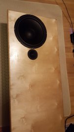
Alright, since no suggestions, I went for the easy route. Made sure the veneer is properly attached (no bubbles, etc) and applied some lacquer to the speakers. Ignored the cracks altogether. Actually quite like it this way, it's got a similar feeling as old log houses. Progress is still ongoing with only 2 layers of lacquer on it, but starting to look really good. Need to work on the surface since I want it to be completely devoid of imperfections.

Here's a sneak peak on how it should look with drivers. It's the left side speaker.
Here's a sneak peak on how it should look with drivers. It's the left side speaker.
Attachments
Last edited:
Looking nice those, you chose a long winded glue method, it works just as well to add glue to both surfaces, bring them together while still wet, and then use a really hot iron, slowly until the moisture dries.
Thanks thanks. I've tried the wet glue method, but it caused warping the last time I did speakers with it. Letting the glue dry in between seemed to work better for me 🙂
Progress is very slow. I'm lacquering, sanding, lacquering, sanding, etc etc. I'm not going to give up until I get the perfect finish. Nothing else is satisfactory.
Progress is very slow. I'm lacquering, sanding, lacquering, sanding, etc etc. I'm not going to give up until I get the perfect finish. Nothing else is satisfactory.
Lost count of layers of lacquer I have on these. Maybe 6? Couple were sanded off because they had too many faults in them.
But still, eventually perseverance paid off, and I was left with a surface I can live with. Next step, affixing drivers and connectors!

But still, eventually perseverance paid off, and I was left with a surface I can live with. Next step, affixing drivers and connectors!
Attachments

What drivers ?
I'm just popping in. Is that a woof with single capped tweet ?
I'm not sure what i am looking at.
I'm just popping in. Is that a woof with single capped tweet ?
I'm not sure what i am looking at.
Hey Norman!
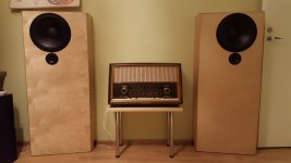
It's ScanSpeak 10F/8424 as mid-tweet and Peerless SLS 12 as woofer/subwoofer.

Plugged the drivers in yesterday, and couldn't resist giving it a listen. Just pseudo-stereo with 1 driver running 1 channel without any kind of filter. Just the left speaker plugged in. Still, the 10F absolutely blew me away with the resolution and clarity it had. I can certainly understand why people think so highly of this little driver. I already knew what to expect from the woofer, but it wasn't a big surprise it performed very well. Overall, just listening to a mono speaker gave me the shivers and made me stay awake way too late just listening to my favourites from Spotify.
The best part? It's only going to get better now with proper crossovers and room correction... 😀
It's ScanSpeak 10F/8424 as mid-tweet and Peerless SLS 12 as woofer/subwoofer.
Plugged the drivers in yesterday, and couldn't resist giving it a listen. Just pseudo-stereo with 1 driver running 1 channel without any kind of filter. Just the left speaker plugged in. Still, the 10F absolutely blew me away with the resolution and clarity it had. I can certainly understand why people think so highly of this little driver. I already knew what to expect from the woofer, but it wasn't a big surprise it performed very well. Overall, just listening to a mono speaker gave me the shivers and made me stay awake way too late just listening to my favourites from Spotify.
The best part? It's only going to get better now with proper crossovers and room correction... 😀
Attachments
looks good for a 4"
https://www.madisoundspeakerstore.c...anspeak-discovery-10f/4424g-4-midrange-4-ohm/
you may only need a tiny bit of hf softening (if any) as we usually listen at lower levels and our ears need the high frequencies to be boosted.
Interesting little bugger.
What crossover point and slope are you thinking ?
Last edited:
norman bates,
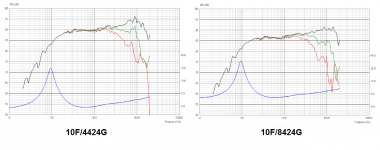
Your link points to 4 ohm version but Mayuri's build use 8 ohm version as linked here and there a bit diffence as seen in attached plots:
https://www.madisoundspeakerstore.c...anspeak-discovery-10f/8424g-4-midrange-8-ohm/
Your link points to 4 ohm version but Mayuri's build use 8 ohm version as linked here and there a bit diffence as seen in attached plots:
https://www.madisoundspeakerstore.c...anspeak-discovery-10f/8424g-4-midrange-8-ohm/
Attachments
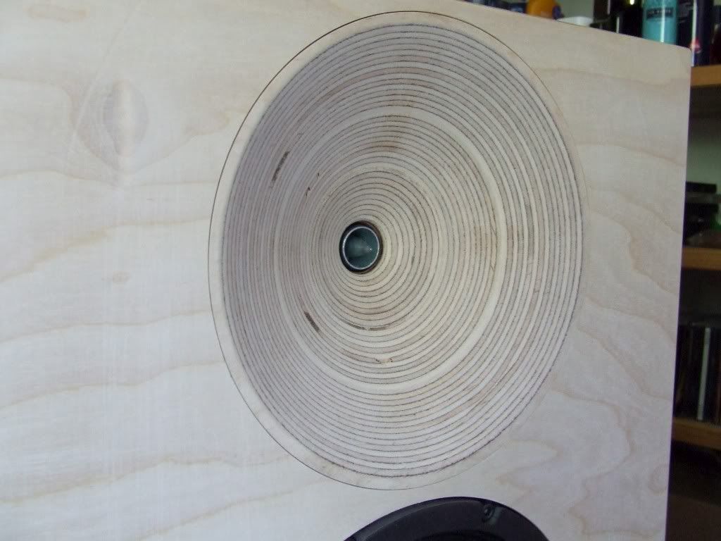
Something I was wondering about is how the supposed 45 degree waveguide on the front baffle will affect the sound? I was thinking of gluing a 12mm + 18mm plywood boards to the 23mm front baffle to time align the drivers better. So, total depth of the waveguide would be 53mm, which to my calculations would align the 10F/8424 pretty nicely with the SLS 12. In the end it would leave me with a waveguide that is 53mm deep and nicely rolls off to the front baffle.
If nothing else, plywood waveguides are gorgeous 🙂
I literally was falling asleep last night trying to figure out how to do this, because a 45* waveguide would not be terribly effective, but a more traditional "flare" with a changing angle would be effective, and would also be gorgeous.
Any idea how to do this? I was thinking jigsaw with varying angles to remove most material, and then hand-sand to finish. It wouldn't look perfect though. CNC mill with a round bit?
Listening without any DSP I think the sound doesn't really need much altering in the HF area. I'm listening the to the driver about 10 degree off-axis. It might change when I get to measurement part. The Dirac Live lets me make my own custom target curve, so for a starter I'll just use the B&K standard curve and mod it to my liking.you may only need a tiny bit of hf softening (if any) as we usually listen at lower levels and our ears need the high frequencies to be boosted.
Interesting little bugger.
What crossover point and slope are you thinking ?
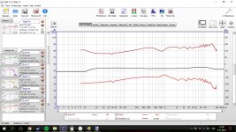
About the crossover, now I start with a basic -48db/oct LR @ 350Hz at it. I think it's something of a compromise between the two drivers distortion measurements (top is SLS 12, bottom is 10F/8424). Did a bit of math later and put a 350Hz Harsch XO at it. Definedly sounds better. This is still without measurements though, so might change when I get some data.
Attachments

Last edited:
For what I found out whilst studying this option was that router with different angle bits would have been one opinion, but a far better one would have been a CNC. Especially if the shop has a machine that can alter the working angle on the go, it's a walk in the park to build a set of waveguides.I literally was falling asleep last night trying to figure out how to do this, because a 45* waveguide would not be terribly effective, but a more traditional "flare" with a changing angle would be effective, and would also be gorgeous.
Any idea how to do this? I was thinking jigsaw with varying angles to remove most material, and then hand-sand to finish. It wouldn't look perfect though. CNC mill with a round bit?
In the end, desided to go against it, and just work the delay in with DSP.
Bit of a edit to the end, happy independence day for all finnish folks possibly checking my thread. I'm going to celebrate the 99 years of being a sovereign nation with a glass of proper brandy and some finnish music in the evening 🙂
Last edited:
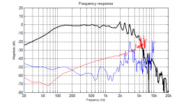
So here come the measurements! These are all taken 60cm away, on-axis, 88cm from the floor (mic height exactly between the two drivers which incidentally is also the listening height). The full-range one is taken with 350Hz Harsch XO (4th order BW on woofer, Bessel with 1,6ms delay on fullrange).
What I can immidiately see is no phase shift on crossover frequency! I uploaded all measurements to my dropbox, and would appreciate if someone with a bit more experience with REW could take a peek. One of the things I'm wondering is the 800Hz bump on the speakers. From what I've simulated with Edge, it seems this is probably caused by the baffle step. Still, didn't expect it to be that steep.
https://www.dropbox.com/s/5ggxg0hssvuuo38/measurements.zip?dl=0
Attachments

From what I calculated, the IR window at 60cm would be around 1,8ms, which I applied to the graphs on my previous post.
If you gate the measurement at 1.8ms then the data will only be valid above 555Hz (1/1.8ms = 1/0.0018) and the frequency resolution will be fairly low too. 5ms is usually a better window as you can splice a near field measurement at about 200Hz and get good data full range.
The window / gate time is used to remove reflections from the measurement. By looking at the IR you can see the reflections and gate before them. The measurement distance is not where you should be gating.
This page from minidsp has some basic information
https://www.minidsp.com/applications/acoustic-measurements/loudspeaker-measurements
- Status
- Not open for further replies.
- Home
- Loudspeakers
- Full Range
- Hi-End Full-Range project