ATTENTION:
It is necessary change the input stepper attenuator to 10K because otherwise the frequency response will be limited due to the input capacitor of 6HV5A.
This mean that the input impedance of this amplifier will be 10K.
----
If you decide to use 1000v instead of 900v is not possible use only 2 x 500v Jensen electr. in serie but you need 3 items in series.

Looks fantastic, Andrea! 😱
I think you are very true ultra-esoteric designer .
Only 2 stages....incredible.
What is the gain of the amp ?
Is it possible use a slightly upper value for the input pot, to say Elma
23 pos 20-30Kohm?
Cheers,
Paolo
I think you are very true ultra-esoteric designer .
Only 2 stages....incredible.
What is the gain of the amp ?
Is it possible use a slightly upper value for the input pot, to say Elma
23 pos 20-30Kohm?
Cheers,
Paolo
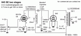
You need only 0.76Vrms as input to get the max power 17W (11.6Vrms on 8ohm) so the voltage gain is
11.6 / 0.76 = 15.26 => 24db
Any CD Player or phono-preampl. can drive it directly without a preampl.
Rout about 2ohm with 10K (Tango X10S) load on 845, 1.7ohm with 11K5 (Lundahl LL1620/90mA AM)
11.6 / 0.76 = 15.26 => 24db
Any CD Player or phono-preampl. can drive it directly without a preampl.
Rout about 2ohm with 10K (Tango X10S) load on 845, 1.7ohm with 11K5 (Lundahl LL1620/90mA AM)
I agree Andrea, no need of any preamp.
Output impedence seems good to my inexpert eyes, I believe better is near impossible without sacrifice the power.
Congratulations, I follow your site and I like very much your designs🙂
Cheers,
Paolo
Output impedence seems good to my inexpert eyes, I believe better is near impossible without sacrifice the power.
Congratulations, I follow your site and I like very much your designs🙂
Cheers,
Paolo
Using 47Kohm in series to the input the band is reduced to 10KHz at -3db so it is easy calculate the input capacitor of the 6HV5A.
Ft(-3db)=1 / (2 * 3.14 * C * R)
C = 1 / (2 * 3.14 * Ft * R) = 1 / ( 2 * 3.14 * 10000 * 47000) =
340pF
This value probably is less because I don't have considered the output impedance of my mesurement system (Clio System).
so with 10K stepper attenuator at the lower position we have a band about
Ft(-3db) = 47KHz
and with 20K
Ft(-3db) = 23KHz
I suggest 10Kohm stepper attenuator but also 20K can be used without problem because only at the lower position the band is limited to the 23KHz.
Important is a drive impedance about 1-3kohm.
Output impedance near 2 ohm is the best value possible with single ended amplifier without feedback.
To get lower value it is necessary reduce to much the output power.
Many commercial vacuum stage amplifiers have value about 3 ohm and declare a double power with these same output tubes.
All the 300b amplifier using 3K load transformers have on putptu impedance about 2.5 - 3ohm.
To get lower value it is necessary reduce to much the output power.
Many commercial vacuum stage amplifiers have value about 3 ohm and declare a double power with these same output tubes.
All the 300b amplifier using 3K load transformers have on putptu impedance about 2.5 - 3ohm.
Oh thanks Andrea,
I understand and agreed on all your points.
I think the Damping Factor is the only "weak" point of any monotriode, also if 5-6 probabily is not that bad , at least if impedance curve of the speaker is relatively flat 😀
Cheers,
Paolo
I understand and agreed on all your points.
I think the Damping Factor is the only "weak" point of any monotriode, also if 5-6 probabily is not that bad , at least if impedance curve of the speaker is relatively flat 😀
Cheers,
Paolo
There's a whole class of modern speakers designed for use with these amplifiers, and many classic designs from JBL, Altec, Klipsch, and Tannoy that work extremely well with amplifiers with relatively high output Z.
From direct personal experience both the JBL C-37 Rhodes, and the original Klipsch Heresy (MKI) work extremely well with source impedances in the 2 - 3 ohm region - in fact the bass can sound very anemic and overdamped with these speakers with amplifiers having very high damping factors.
It is a question mainly of whether or not the designer assumed the amplifier used will be a perfect voltage source, the flatness of the load impedance across the audio band, and whether or not the efficiency is high enough to get the spls and dynamics expected with the available power.
In any case I prefer design all my amplifier with max 1.7ohm to get good result on normal and common loudspeakers with a nominal impedance of 8ohm.
I have got good result also driving full-range speakers with 16ohm like AER and FullrangeSpeaker.
In the case you have 4ohm loudspeakers with 2 woofer in parallel consider to change these before to start the project of a single ended amplifier.
I have got good result also driving full-range speakers with 16ohm like AER and FullrangeSpeaker.
In the case you have 4ohm loudspeakers with 2 woofer in parallel consider to change these before to start the project of a single ended amplifier.
Hi guys,
I know speaker very well, unfortunately the opposite is for amplifiers
For now I can only dream a SE triode amp with 1000v😱
Also if you have to take in mind that I listen with a power follower 97
tube driven😉 Not bad , even comparating with a 300B 😀
Andrea, please I have e-mailed you last week for a question about LC
PSU for my power follower but maybe you have not received it😕
Cheers,
Paolo
Paolo, send me again the email about PF99
------------------
I am waiting the 100H Lundahl choke to procede to the final measurement and sonic performances test
------------------
I am waiting the 100H Lundahl choke to procede to the final measurement and sonic performances test
audiodesign said:Just to post last schematics.
How does that filament work with no voltage?

audiodesign said:Galon,
What you mean ?
There is a mistake in your schematic that shows the 845's 10V filament supply shorted directly together and to ground. The 10V connections are just drawn in the wrong spot.. 😀

Hi Andrea,
I have seen that you changed some valueas on schematic.
Regarding the input, as our telephone conversation where I asked you the Cag of 6HV5A (there are no spec on data sheet) because with a gain of 150 I supposed (for the Miller effect) the input cpacitance was not low and you calculations are good.
Regarding the grid resistor of 845 now I am almost agree with you.
What I have seen on specification of Lundhal 1620 is the max Vrms at the primary with the configuration you choose; it is reported 380 vrms ( is not specified the frequency, unfortunately), this means that with a ratio of 38:1 I must have 10 Vrms at the 8 ohm load (about 12w rms), this can be a limit.
Another possible limit is the current suggested for this trafo, 80 mA (for the configuration you choose); it seems too low for this application.
The problem is always handling a great current swing at low frequencies.
Bye
Walter
Lundahl on the LL1620 datasheet declare a max primary voltage of 380Vrms at 30Hz (13W on 8ohm) but I have demostrated many times on my projects that this value is not a real limit.
In any case with a real loudspeakers connected to this amp. you can get many more power because the impedance will go to lower value and the same LL1620 can give 25W on 4ohm.
The Lundahl transformers are semi/custom so you can order without problem a LL1620/80mA, LL1620/90mA and LL1620/100mA.
In any case with a real loudspeakers connected to this amp. you can get many more power because the impedance will go to lower value and the same LL1620 can give 25W on 4ohm.
The Lundahl transformers are semi/custom so you can order without problem a LL1620/80mA, LL1620/90mA and LL1620/100mA.
The inductance value of the primary on LL1620 must be considered if you change current (gap) but it is simple to calculate.
If LL1620/60mA have 60H
LL1620/80mA will have 60 * 60 / 80 = 45H
LL1620/100mA will have 60 * 60 / 100 = 36H
changing the inductance value will chage the low frequency band as seen (see 211/845 compare calc.)
If LL1620/60mA have 60H
LL1620/80mA will have 60 * 60 / 80 = 45H
LL1620/100mA will have 60 * 60 / 100 = 36H
changing the inductance value will chage the low frequency band as seen (see 211/845 compare calc.)
- Home
- Amplifiers
- Tubes / Valves
- Hi-end 845 with only two stage