Magnetic Zero Crossings
Hi Andrea,
Not to distract too much from the discussion on your 2 stage 845
amplifier, which is a cool concept as is the HV pulse regulator triode
as a high mu driver (gm=65,000) and this one has a nice low Rp.
But since you brought it up, the notion of this magnetic "zero crossing"
has me intrigued. I refer particularly to the "kinked" dashed line in
figure 4 of the article you reference above.
The thing is, my own experience with magnetics doesn't support
the existence of the kinked curve as a magnetic operating loop
of a core in any transformer. I'm not saying it doesn't exist, but
the only place I've ever seen it is "penciled in" on a B-H diagram
to explain the deficiencies of a push-pull audio output stage.
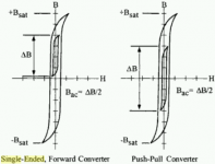
My understanding of what's happening is more like the diagram I
attached from a magnetics text. The outer loop is the saturation
loop, going to saturation at each end of the loop. It's a characteristic
of the core, frequency, etc.
The inner loop, or minor loop, is the actual signal drive at a particular
level below saturation. There is no kink in the middle of either SE
or PP minor loops shown. As I understand, there is no kink in the
middle of any minor loop. The hysteresis occurs at the ends, and this
is where the direction of magnetization reverses (not in the middle
where the polarity of the drive voltage changes). This is as I
understand because the flux changes when the direction of the
voltage changes i.e. positive-going to negative-going and back.
The article you reference also seems to have some inconsistency
in the use of coercive force with more common usage as synonymous
with field strength H. I think there is also some confusion between
hysteresis and small-signal magnetizing current.
I do believe there is a difference between SE and PP due to the
effect of the air gap, and I would recommend Menno Van Der Veen's
2007 AES paper looking at small-signal permeability within the region
of the core magnetizing current. To summarize, he suggests that a
larger core with an air gap, as necessitated by the SE transformer
design, holds it's relative permeability down to smaller signal levels.
Perhaps because the gap lowers permeability to start with?
Higher permeability at low signal levels means higher inductance
and lower distortion, which gives better preservation of low level
detail. There are other ways to mitigate the low level issue like
core material with lower remanence, lower Rp of the output tube.
But basically that effect would be extreme widening and squaring of
the minor B-H loop for very small signal levels, resulting in distortion
and loss of low level detail, as opposed to a kink in the large signal
B-H loop.
At least this is my current understanding.
Cheers,
Michael
1. LOW LEVEL AUDIO SIGNAL TRANSFER THROUGH TRANSFORMERS
CONFLICTS WITH PERMEABILITY BEHAVIOR INSIDE THEIR CORES
Menno Van Der Veen, 122nd AES Convention Paper, May 2007
audiodesign said:About the use of PP transformer with no gap we must consider that:
SE OPTs largely avoid the hysteresis effect from maintaining magnetization in a linear region
from:
http://homepage.mac.com/tlinespeakers/vaughn/downloads/SE-v-PP-Part2.pdf
Hi Andrea,
Not to distract too much from the discussion on your 2 stage 845
amplifier, which is a cool concept as is the HV pulse regulator triode
as a high mu driver (gm=65,000) and this one has a nice low Rp.
But since you brought it up, the notion of this magnetic "zero crossing"
has me intrigued. I refer particularly to the "kinked" dashed line in
figure 4 of the article you reference above.
The thing is, my own experience with magnetics doesn't support
the existence of the kinked curve as a magnetic operating loop
of a core in any transformer. I'm not saying it doesn't exist, but
the only place I've ever seen it is "penciled in" on a B-H diagram
to explain the deficiencies of a push-pull audio output stage.
My understanding of what's happening is more like the diagram I
attached from a magnetics text. The outer loop is the saturation
loop, going to saturation at each end of the loop. It's a characteristic
of the core, frequency, etc.
The inner loop, or minor loop, is the actual signal drive at a particular
level below saturation. There is no kink in the middle of either SE
or PP minor loops shown. As I understand, there is no kink in the
middle of any minor loop. The hysteresis occurs at the ends, and this
is where the direction of magnetization reverses (not in the middle
where the polarity of the drive voltage changes). This is as I
understand because the flux changes when the direction of the
voltage changes i.e. positive-going to negative-going and back.
The article you reference also seems to have some inconsistency
in the use of coercive force with more common usage as synonymous
with field strength H. I think there is also some confusion between
hysteresis and small-signal magnetizing current.
I do believe there is a difference between SE and PP due to the
effect of the air gap, and I would recommend Menno Van Der Veen's
2007 AES paper looking at small-signal permeability within the region
of the core magnetizing current. To summarize, he suggests that a
larger core with an air gap, as necessitated by the SE transformer
design, holds it's relative permeability down to smaller signal levels.
Perhaps because the gap lowers permeability to start with?
Higher permeability at low signal levels means higher inductance
and lower distortion, which gives better preservation of low level
detail. There are other ways to mitigate the low level issue like
core material with lower remanence, lower Rp of the output tube.
But basically that effect would be extreme widening and squaring of
the minor B-H loop for very small signal levels, resulting in distortion
and loss of low level detail, as opposed to a kink in the large signal
B-H loop.
At least this is my current understanding.
Cheers,
Michael
1. LOW LEVEL AUDIO SIGNAL TRANSFER THROUGH TRANSFORMERS
CONFLICTS WITH PERMEABILITY BEHAVIOR INSIDE THEIR CORES
Menno Van Der Veen, 122nd AES Convention Paper, May 2007
Attachments
Michael,
This was I mean
Are we sure that a PP transformer with no gap and with dc compensation have same linearity of a SE transf. ?
With PP transf. the signal pass to zero crossing area.
--------------
I have forgot 2 points in my summary of yesterday.
1) About input step-up transformer:
It is true that normal CD player have low output resistance near 300-600 ohm able to drive an amplifier with input step-up transformer but I think that a DIY using a 845 amp. like this one does not accept to ear music with a normal CD Player output stage using op-amp. and he should have modified it with vaccum tube stage or output transf. to skip all op-amp.
2) About power supply volatge more than 1Kv
.....
Hi again Andrea,
No, not quite. Do not use a PP! I propose a LL18mA but to compensate with reversed current through the secondary(it is all in the schematic).
So if you have this 18mA SE and want to run 25mA through it you have to compensate with something like 10mA in the opposite direction through the secondary. The net current in the core will then be below 18mA!
I guess the optimal compensation current and airgap will have to be determined through tests.
You can find more info on Dave Slagles www.intactaudio.com forum in the "current cancellation" section. He has also come to the conclusion that the gap should not be eliminated in the purpose to get max inductance.
Did some sims and these also shows that at least 100H should be used but preferably more. So maybe a 10mA Lundahl with 15mA compensation?
By the way both Michael and I have lately participated in threads in this section and also made experiments with mainstoroids as both OPTs and ITs. Then there is no other option but to treat them as PPs.
I see, you propose to compensate the dc current on the PP interstage transformer with bias voltage
No, not quite. Do not use a PP! I propose a LL18mA but to compensate with reversed current through the secondary(it is all in the schematic).
So if you have this 18mA SE and want to run 25mA through it you have to compensate with something like 10mA in the opposite direction through the secondary. The net current in the core will then be below 18mA!
I guess the optimal compensation current and airgap will have to be determined through tests.
You can find more info on Dave Slagles www.intactaudio.com forum in the "current cancellation" section. He has also come to the conclusion that the gap should not be eliminated in the purpose to get max inductance.
Did some sims and these also shows that at least 100H should be used but preferably more. So maybe a 10mA Lundahl with 15mA compensation?
By the way both Michael and I have lately participated in threads in this section and also made experiments with mainstoroids as both OPTs and ITs. Then there is no other option but to treat them as PPs.
Lars,
but in this situation we have the same problem of zero crossing for a part of signal
------------
2) About use the 6HV5A with more than 1Kv
Richard, told that 6HV5A give a better sound with an anode voltage of 1000v or more
It is possible use for both stages 1100v instead of 900-950v but we must limit the bias current of 845 because we have a max power dissipation of 100w.
If we consider a max 90w to get a long life time of vaccum tube and with 1100v the bias should be Ia=90/1100=81mA.
Yesterday evening at 950v I have measured half distortion with 100mA than the value at 80mA so before decide to go to higher voltage it is necessary a test and other measurement.
Use different power supply voltage for driver and output stage is possible but this will increase a lot the cost.
audiodesign said:
<snip>
Kevin have suggested to use the 211 instead of 845 because it have more voltage gain 12 instead of 5.3.
But with 211 it is necessary use an output transformer with higher turn ratio to get the same good damping factor on normal loudspeakers so the grid voltage necessary is near.
In many case a 23K output transf. is more expensive of a 10-11K.
Tell me if I have forgot something.
Actually I didn't suggest you use the 211, I was simply commenting on the fact that I was doing something quite similar with the 211 because that is what I have on hand. (They came to me at a good price.) I think the 845 design you are talking about is a valid choice for what you are doing. My needs are very different, including needing a much higher source impedance because of the design of my diy speaker system. (I need a ~2.5 ohm source impedance to maintain the proper bass alignment in my system.)
FWIW I have not heard that it is possible to build good 23K to speaker impedance opts that can handle an appreciable amount of power and have good frequency response as well - so I think that rules out the 211 for your application.
Kevin,
you can go parafeed. I got quite remarkably good results with Mike's irons (FS100PF).
In case you do not find any OPT ... resell the 211s to me 😀
Gianluca
you can go parafeed. I got quite remarkably good results with Mike's irons (FS100PF).
In case you do not find any OPT ... resell the 211s to me 😀
Gianluca
Andrea,
I totally agree about a "part of signal". But the way I see it, it will not cross before the AC-signal passes the standing 18mA DC-current. So if bias is set to 25mA it is the last 7mA that maybe could be a problem. And at what signal-level is that with the 6HV5A?
I read the article and it is mentioned that the good thing about SE is "more coherent and more detailed than PP at low volume". So i think this virtue should then be kept with a current compensated transformer like above.
So which is best, a choke and a cap or a compensated SE? Think this is up to the builder/listener to judge.
I´ll make my friend Hoktuna try this theory in a GM70 together with 6C45 and a 18mA LL1660 we are planning. For what we have heard/read the 6C45 is happier with a standing current well over 20mA.
Lars,but in this situation we have the same problem of zero crossing for a part of signal
I totally agree about a "part of signal". But the way I see it, it will not cross before the AC-signal passes the standing 18mA DC-current. So if bias is set to 25mA it is the last 7mA that maybe could be a problem. And at what signal-level is that with the 6HV5A?
I read the article and it is mentioned that the good thing about SE is "more coherent and more detailed than PP at low volume". So i think this virtue should then be kept with a current compensated transformer like above.
So which is best, a choke and a cap or a compensated SE? Think this is up to the builder/listener to judge.
I´ll make my friend Hoktuna try this theory in a GM70 together with 6C45 and a 18mA LL1660 we are planning. For what we have heard/read the 6C45 is happier with a standing current well over 20mA.
Gluca said:Kevin,
you can go parafeed. I got quite remarkably good results with Mike's irons (FS100PF).
In case you do not find any OPT ... resell the 211s to me 😀
Gianluca
Hi Gianluca,
I shouldn't have any problem sourcing opts for my amplifier design, and I have access to a loaner pair of the FS-100 at this point which might be fine - otherwise I will have some wound.. 😀
I have also been thinking about the parafeed option, and that is not ruled out at this time.
Using this simple power supply I ear no noise on my reference loudspeakers with sensibility near to 88-89db
http://www.audiodesignguide.com/TheMonitor2/index.html
but if you use high sensibility drivers probably it is necessary a center trimmer or a dc power supply for the filaments of the 845.
----
In a first comparation test with my 845 ver. 3 (beta release) the sound of this new amp. is more clear and detailed.
This evening I have replaced on both the amplifiers the interstage capacitor with a Mundorf Mcap Supreme silver/gold/oil 2.2uF 1200Vdc.
The Jensen copper film paper in oil add some bad effect on sonic performances.
After this modification the sound of these two amps. is very similar and it is very difficult to decide which is better so I will wait some my friends to have an objective result.
Hi there
Ciao Andrea
You should try a monster beefy SE IT made by Bartolucci
http://www.ricercaesviluppo-fano.it/it/index.php?option=list&cat=7
called INT6 (or maybe INT3 ) :
INT.6
7000Ω
80mA
15W
100 Hy
203Ω
Ω
3Hz / 42kHz
4,2 Kg
Are these measures real?
Probably it's bigger than your little swedish OPT.
regards
Never tested Bartolucci products but I have read good comments about these transformers.
Actually I use only amorphous cores by Lundahl because there is a good increment in sonic performances if compared to the same model with normal core.
So it is impossible to know if is better a normal core like the Bartolucci INT6 or a choke+good cap. on the signal path.
I will ask to Lundahl the possibility to develop a new interstage with amorphous core SE to get 100H with a gap for 30-50mA.
This transformer could be used also to make test using 2A3 like driver.
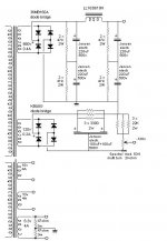
Some notes about power supply used.
As diode bridges could be used KBU8M or UF5408 in the same configuration.
Someone add little caps in parallael to diodes to reduce the noise created by current peak generation.
The separation of transformers (filaments and anodic) is suggested only if you think to use in the future dc filaments because in this case the peak generated on diode bridge create noise and this will arrive amplified on anodic secondaries.
The anodic voltage with these caps. can be used for both channel but off cource a separation will give the best result.
If you will separe the anodic it is possible reduce all the Jensen caps to 100uF instead of 220uF.
It is possible use the same anodic secondary and separate the channels with 2 choke.
The Jensen electrolytic since to be very good but it is possible use Solen 50uF 1500v MKP or new Mundorf 100uF 550v Tubecap in series.
The drive both channels the bias circuit need another Spectrol 534 trimmer and another set of 3 x 22kohm resistor to set the rigth bias for each 845 and separate the grid.
Hi,
another solution can be a Gomes circuit ( is easy to find around the web) with ECC83 (or 12BZ7).
With a +Va of 550 Vdc you find a grat swing, a gain about of 75 with an output impedance about of 600 ohm.
You can also trim the load resistor to keep the THD very looe.
This circuit is not so dependent form the load as the normal totem.
With a 1:2 input trafo we can get a gai of 150 with a reasonable THD.
In origin this circuit was developped from Gomes to drive a p-p of 211; in input he used a 1:1+1 trafo to have a phase plit from the beginning.
Bye
Walter
Walter,
I never have considered to drive a 845 with the catode of a little 12AX7 because these tubes also in A1 class get some grid current so it are necessary a minimum of 10-20mA in driver stage.
I have measured 130uA (0.13mA) of grid current with 10Vrms on loudspeakers output with 945Vdc.
It is also usefull go in A2 for some peak to increase power.
In any case the Gomez circuit cannot be considered a sinlge stage.
-----------
new schematic here
Attachments
There is actually one triode out there with descent Gm and mu over 100. The triode section of the 6F12P can deliver over 90V rms at Ua 200V and Ia 10ma. But a high inductance will be needed as Ri is in the ballpark of 6k at 10mA.
I have measured the ten I bought from Russia in my AVO and linearity seems to be quite good. Have not tried them in circuit yet, though.
The pentode section has a Pa of 5W and could maybe be used as a DC-coupled CF if driving into A2 range if called for.
I have measured the ten I bought from Russia in my AVO and linearity seems to be quite good. Have not tried them in circuit yet, though.
The pentode section has a Pa of 5W and could maybe be used as a DC-coupled CF if driving into A2 range if called for.
Andrea,
with a bias pont at -120 vdc, at the best you can have 240V pp to drive the 845; this means that you can have 11 Veff on 8ohm=15 Wrms.
The problem, for me, is that with 6HV5 in this configuration you can loose some signal due the output impedance of the stage with the load 20k (the grid resistence of 845) .
With the Gomes ( for me is a single stage) you have a very low output resistance that can drive without problem the grid also in A1; if you have mesaured 0,13 mA, with Gomes you can reach about 20 time more the current.
For A2 i have some doubt also with the 6HV5.
Ciao
Walter
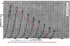
Here the output characteristics of the 845 tube with load line at 11500 ohm and operation point at 90mA 900V.
Plot the load line is simple I=900/11500=0.078A=78mA so to find the upper current point of the line I=78mA + 90mA = 170mA.
The calculation of Walter is correct but the power in these conditions is the same for any kind of driver.
Some peak on A2 will allow to increase a little the power if the driver will have enougth bias current.
Attachments
Using the SE Amp CAD by GlassWare (http://www.glass-ware.com) it is very easy verify that increase the power supply does not resolv the problem of power output limitation.
Follows the result of 2 plot with 900v 90mA and 1100v 80mA.
It is true that with 1100v we get more power 18w instead of 15w but at the same power out (15w) the distortion if more high with 1100v.
Probably a good compromize should be 1000v 90mA.
see here:
http://www.audiodesignguide.com/Claudio845/Simul1100v.gif
(sorry for the external link but this is to large for the forum)
A method used often to get more power from 845 is reduce the load to 7-8K instead of 10-11k but in this case the output resistance will go to 2.5-3ohm so it is not acceptable to drive normal loudspeakers because damping factor is too low.
Here the last measurements
Vp=1000V
Ia=90mA
Rg=50K MK132 Caddock
Ci=2.2uF 1200v Mundorf Supreme
Rk=100ohm
Ck=220uF
La=20H to modify to 100H
11.6Vrms on 8ohm with a perfect distorstion decay
Pout=11.6*11.6/8ohm=17W
-0.5db at 20000Hz
-3.0db at 25Hz with 20H so 5Hz with 100H
Vp=1000V
Ia=90mA
Rg=50K MK132 Caddock
Ci=2.2uF 1200v Mundorf Supreme
Rk=100ohm
Ck=220uF
La=20H to modify to 100H
11.6Vrms on 8ohm with a perfect distorstion decay
Pout=11.6*11.6/8ohm=17W
-0.5db at 20000Hz
-3.0db at 25Hz with 20H so 5Hz with 100H
Attachments
- Home
- Amplifiers
- Tubes / Valves
- Hi-end 845 with only two stage