Andrea
Try NOS Tungsram PV200/1000 (200mA, 1000V, 4V/3.4A heater) rectifier tubes.
http://www.elektroncso.hu/cikkek/tung_pv200_1k.jpg
Try NOS Tungsram PV200/1000 (200mA, 1000V, 4V/3.4A heater) rectifier tubes.
http://www.elektroncso.hu/cikkek/tung_pv200_1k.jpg
Andrea,
I personally like the idea of s SS pair or bridge depending on transformer winding availability to make the DC, then gate it through a slow warmup TV damper tube. Place the PS filter components after the damper diode. I like the looks of the 6BL4 for such a purpose but since your B+ line is dangerously close to the peak permissable cathode positive against heater voltage limit, I think it wise to assign a separate filament heat winding to power the damper tube and allow the heater to float high tied to the cathode with a small resistor. You could put two 6BL4's in parallel for a more bullet proof design. In fact with the above configuration you could actually use one or more parallelled TV dampers that are more commonly available. I suggested 6BL4 as it is a big sexy one with 8 watts PD and 200 mA continuous output current rating. 6AU4 is much more plentiful where I live and a pair would do nicely here.
http://www.mif.pg.gda.pl/homepages/frank/sheets/137/6/6AU4GT.pdf
We must consider 2 elements in the power supply design with vacuum tubes:
1) vacuum tubes with cap anode is dangerous
2) using full wave single diode power supply we will have a very high voltage in the amplifier 2 x 800 volt so 1600v that increase the dangerousness level
P.S. in any case I am not sure that vacuum tube diodes make a difference in the sound
Here 2 simulation with the usefull tool PSU Designer II by Ducan Amplification
Attachments
It is also possible use this hybryd design with some modifications to use less vacuum diodes.
http://www.lundahl.se/hybrid_pow.html
*********************************************
GLOBAL NOTE
This is a expert only project because the high power supply voltage, about 1000V, it can kill!
Keep always one hand, left hand is better, close to your back.
For the high voltage connection use only good wire with WVDC (Working Voltage Direct Current ) of 5000V.
audiodesign said:It is also possible use this hybryd design with some modifications to use less vacuum diodes.
http://www.lundahl.se/hybrid_pow.html
*********************************************
GLOBAL NOTE
This is a expert only project because the high power supply voltage, about 1000V, it can kill!
Keep always one hand, left hand is better, close to your back.
For the high voltage connection use only good wire with WVDC (Working Voltage Direct Current ) of 5000V.
Andrea,
This is a good technique which I employed to get much greater B+ voltage (620 V B+) from my xfmer while still using only a single 5V4 rectifier tube in my low power SET A2 amp. I was not suggesting that you use this circuit.
The damper diodes I suggested do not use anode cap connections. Granted, the 866's and 3B28's did. I agree wth you they create safety issues.
What I did suggest was that you make either a two diode solid state employing xfmer CT full wave rectifier, or a solid state full wave bridge and then run the DC output, unfiltered yet, through a pair of 6AU4 TV dampers in parallel (they are only good for 190 mA MAX each) to give it time delay. The choke input to the supply filter goes to the two 6AU4 parallelled cathodes. Isolated 6.3 VAC filament winding for the two 6AU4's was recommended. You could probably even use the very common 6AX4 as you are paralleling two damper tubes here. Should check specs on that.
http://www.mif.pg.gda.pl/homepages/frank/sheets/137/6/6AX4GT.pdf
Only good for 125 mA per tube. That is still enough for you but close to the limit. 6AU4GT is WAY better.
Socket pinout is the same so you could upgrade any time.
With the choke input (5-10 Henries) you can use a large filter capacitor without worry about damaging the vacuum tube rectifier damper diodes. I am going to guess that is how you destroyed your 6D22's. Too much electrolytic cap hanging directly off the 6D22's.
This is the circuit where I have used the 6d22, choke input
http://www.audiodesignguide.com/my/845a_sch.jpg
http://www.audiodesignguide.com/my/845a_sch.jpg
sorry again
single 1N5406 are not good for 1Kv output
the schematic is only to see the different connections
single 1N5406 are not good for 1Kv output
the schematic is only to see the different connections
audiodesign said:soory some mistake in the previous schematic
#3, the one on the far right is good (what I mean) BUT, replace the resistor with your 4 Hy series choke circuit, the rest of the circuit here
http://www.audiodesignguide.com/my/845a_sch.jpg
looks fine.
audiodesign said:This is the circuit where I have used the 6d22, choke input
http://www.audiodesignguide.com/my/845a_sch.jpg
Hi Andrea,
I noticed you did not use any sort of snubbing around the chokes or the rectifiers, this may have contributed to the demise of your 6D22s as when the rectifiers are not conducting you may see spikes of many KV at the cathodes of your 6D22 depending on the behavior of your chokes and their associated parastics. You might want to look into this. Old ARRL handbooks may give some insight into this issue in their power supply design chapters. With these sorts of voltages and choke input you do need to use rc networks either across the chokes and/or from the common cathode point to ground. This will help to kill the spikes. High voltage silicon diodes to ground may also help in some instances. (Normally reverse biased in operation.)
Bob,
in my 845 amp.
http://www.audiodesignguide.com/my/845a_sch.jpg
I have found some problems with input chokes
Input chokes work in different condition than other chokes because these manage a lot of ripple voltage.
For this use it is necessary specific products with high max ripple voltage and 2 x LL1668 was not enough.
I have found many noise and vibrations because the LL1668 have a max ripple of 300v so 2 items arrive to only 600v.
To have a good choke input without noise and vibrations should be necessary 3 x LL1668 to arrive to a max ripple voltage of 900v.
So in this new amp. with 1000v the 3 x LL1668 could be too low.
I don't see other components on the market for this purpose.
I remember it is important use always choke with low Rdc.
Kevin,
I have calculated the RC network to add in parallel to the choke input with these formula:
2*pi*F= 1/sqrt(L*C)
if the frequency is 50Hz after the diode bridge we will have 2 x 50Hz = 100Hz
2*3.14*100 = 1/sqrt(L*C) so
sqrt(L*C) = 1 / 2*3.14*100 = 1 / 628
L * C = (1/628)^2 = 2.5E-6
C = 2.5E-6 / L
if L=8H C=0.31uF
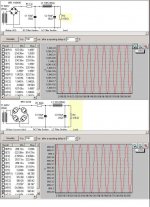
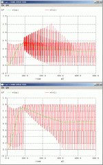
Here the Winspice simulation output of a simple choke input power supply with and without the RC network.
It is clear that the RC network is necessary to prevent high voltage spikes in start-up phase (second plot with RC).
vl = voltage after diode bridge
ou = output voltage
For RC network I have used a series of 100ohm and 0.31uF in parallel to the choke L=8H Rdc=57ohm, filter cap. 100uF load 5Kohm
I have calculated the RC network to add in parallel to the choke input with these formula:
2*pi*F= 1/sqrt(L*C)
if the frequency is 50Hz after the diode bridge we will have 2 x 50Hz = 100Hz
2*3.14*100 = 1/sqrt(L*C) so
sqrt(L*C) = 1 / 2*3.14*100 = 1 / 628
L * C = (1/628)^2 = 2.5E-6
C = 2.5E-6 / L
if L=8H C=0.31uF
Here the Winspice simulation output of a simple choke input power supply with and without the RC network.
It is clear that the RC network is necessary to prevent high voltage spikes in start-up phase (second plot with RC).
vl = voltage after diode bridge
ou = output voltage
For RC network I have used a series of 100ohm and 0.31uF in parallel to the choke L=8H Rdc=57ohm, filter cap. 100uF load 5Kohm
Attachments
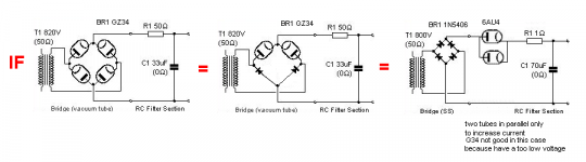
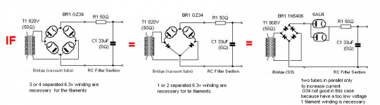
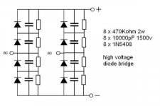
here the schematic of the discrete diode bridge to use using a transformer with a single secondary at 800v
using vaccum diodes in the power supply some voltage will be lost on these so consider 20-50v more on secondary
using vacuum diodes the input capacitor should be no more than 10-30uF see datasheet of tubes.
3 x 100uF 500v in series are 33uF
using vaccum diodes in the power supply some voltage will be lost on these so consider 20-50v more on secondary
using vacuum diodes the input capacitor should be no more than 10-30uF see datasheet of tubes.
3 x 100uF 500v in series are 33uF
Attachments
Bob,
I have found the Hashimoto C-15-200CH choke input with 600Vmax and a relative low Rdc but also in this case we need 2 choke to arrive to 1200Vmax
http://www.eifl.co.jp/index/export/hashimoto/hashimoto.html
I have found the Hashimoto C-15-200CH choke input with 600Vmax and a relative low Rdc but also in this case we need 2 choke to arrive to 1200Vmax
http://www.eifl.co.jp/index/export/hashimoto/hashimoto.html
Here the final all Tango version schematic.
the measurements has been sent in a previous reply.
17W on 8ohm with 1-2% thd
necessary 0.5-0.6Vrms to get max good output.
sonic peformances comments soon.
to get the max power I have set the bias to 90mA Vg=133v but the Tango X-10S has been design for only 70mA.
the measurements has been sent in a previous reply.
17W on 8ohm with 1-2% thd
necessary 0.5-0.6Vrms to get max good output.
sonic peformances comments soon.
to get the max power I have set the bias to 90mA Vg=133v but the Tango X-10S has been design for only 70mA.
Attachments

Probably I have found a good input choke
SOWTER 8901 Plate Choke 50 Henry 100 mA
Plate chokes provide an anode load for parafeed output stages ac coupled to a Mumetal single ended output transformer. Supports a signal of 1000 V at 30 Hz. Fully shrouded package colour coded leads. weight 4.6Kg. Size N
Information
Price: £113.58
Rdc=150ohm
not bad!
25mA on 6HD5A + 75mA on 845 = 100mA so one per channel
what you think about ?
audiodesign said:Bob,
I have found the Hashimoto C-15-200CH choke input with 600Vmax and a relative low Rdc but also in this case we need 2 choke to arrive to 1200Vmax
http://www.eifl.co.jp/index/export/hashimoto/hashimoto.html
Andrea,
I am afraid that I shall not be of too much help to you now. Those parts are really, really expensive. All my experience is in finding second hand parts bought cheap and then trying to use them in ways perhaps beyond how they were designed. My success record is extremely good but it is not so much based on study of specs and computer simulations, just trial and error on the lab bench. I never gave any thought before to the spec of AC in the power supply choke before quite frankly. That was never shown in the sorts of catalogues that I use for reference, such as the old Hammond Transformer catalogues. They give you L and series R, current rating. That's it.
I found a large swinging choke rated at about 300 mA and about 5-15 Henry made by Chicago Transformer co. at a Hamfest years ago that I used as the input choke filter on the 1050 volt power supply to my 805 SET stereo amp power supply. It works great! I had to deal with the diode switching noise of the bank of 1kV @3 amp diodes that make my FW bridge. I had to make a mu metal shield to place around the choke as it's leakage flux from the core gap was inducing hum in the small signal circuits under the chassis in one channel. You could stick a wrench to the gap! It was like the lifting magnet on a scrapyard crane! The choke is mounted under the chassis. If the plate xfmer is turned on without a load the B+ sails up to about 1600 VDC. My cap bank can handle 2000 so no problem there but it puts real stress on the OPT primary and I get faint snapping noises in the speakers that I think indicate what is referred to as PD (Partial Breakdown) of the winding insulation system. That is scary so I make sure that there is a load present before I turn on the B+ switch (switches primary on to the plate xfmer. This is merely to wait 30 seconds after turning on the main power switch to allow all the tubes to reach stable cathode emission temp. Since the load is there waiting my B+ only rises to 1050 volts with no dangerous overshoot. This amp has been reliable now for a couple of years of heavy use. Regulation is excellent. B+ only varies 1-2 volts from zero to 45 watts per channel x 2. That is about 0.1-0.2%
If it were me doing your amp and I did not have a proper choke already at hand I would be making my own input chokes from microwave oven power xfmers. The HV winding operates at about 2 kVAC, 60 Hz and 500 mA continuous current is no problem as a choke. I find I do not have to cut a core gap, but you do need to deal with the fact that the inside connection of the HV winding is connected to the core. If you place the choke in the negative side of the power supply the choke output terminal could be at chassis potential! I don't mind spending some time and effort in order to save $500 for a transformer I might need, especially chokes. Fortunately they are not rocket science.
audiodesign said:Probably I have found a good input choke
SOWTER 8901 Plate Choke 50 Henry 100 mA
Plate chokes provide an anode load for parafeed output stages ac coupled to a Mumetal single ended output transformer. Supports a signal of 1000 V at 30 Hz. Fully shrouded package colour coded leads. weight 4.6Kg. Size N
Information
Price: £113.58
Rdc=150ohm
not bad!
25mA on 6HD5A + 75mA on 845 = 100mA so one per channel
what you think about ?
That sounds like a sweet modulation choke. At 50 H it is way too big for a power supply choke. I would not use it in a power supply but it would be nice to have for a parafeed SET output stage with tubes like 805, 845, 813, etc. Then you could use a much less expensive P-P output xfmer with a coupling cap.
Whatever I did with that particular choke if I was using one would be to hard wire a air spark gap across it to protect it in case it got into resonance or was fully charged and then open circuited once. The back EMF could easily get high enough to break down it's own insulation system and destroy it. You see such spark gap protectors on big chokes in old tube type AM radio station transmitters all the time.
ok Bob,
so about the use of input choke in a power supply with 1000v we can make these considerations:
1) there are very few components on the market designed to be used like input chokes and in all the ase is necessary a serie of 2 or 3 items to arrive to 1000v.
3 x Lundahl LL1638 10-20H 200-400MA (3x300v Rdc=3x36ohm
2 x Hashimoto C-15-200CH 15H 200MA (2x600v Rdc=2x130ohm)
2 x Hashimoto C-25-150CH 25H 150mA (2x700v Rdc=2x200ohm)
2 x Sowter 8971 10H 200mA (2x600v Rdc=2x151ohm)
the Lundahl seem to be the best for the lower cost and lower Rdc.
2) As input choke it is possible to try normal type without a specification of max voltage but it could not considered as a serious design and the effect are not expectable.
-----------
I have used input choke in design with lower voltage like this one:
http://www.audiodesignguide.com/my/pse3.html
I suggest this design if you have medium-high loudspeakers (95-100db) or little room because the output power should be about 4-5w.
- Home
- Amplifiers
- Tubes / Valves
- Hi-end 845 with only two stage