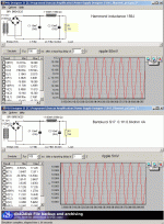
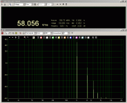
I have started a webpage to show all the power supply solutions.
http://www.audiodesignguide.com/Claudio845/ps_design.html
http://www.audiodesignguide.com/Claudio845/ps_design.html
audiodesign said:ok Bob,
<snippage>
2) As input choke it is possible to try normal type without a specification of max voltage but it could not considered as a serious design and the effect are not expectable.
-----------
I have used input choke in design with lower voltage like this one:
http://www.audiodesignguide.com/my/pse3.html
I suggest this design if you have medium-high loudspeakers (95-100db) or little room because the output power should be about 4-5w.
Andrea,
Is your goal to make one only superb amplifier for your own personal use or to offer a kit of some sort which can be duplicated by others? If the first then what does it matter if the design isn't text book perfect if it starts reliably in cold weather, rides smooth and still gets over 100 km per litre of fuel?
In my case I build only for myself and pride myself enormously in using ingenuity and recycling what our effluent* society throws away to save me money. 😉
* Misspelling 'affluent' was deliberate.

Yesterday I have received the new Bartolucci interstage (INT8CNEW) so I have created a webpage with all the measurement until here.
I am still waiting the Bartolucci OPT for the final compare.
http://www.audiodesignguide.com/Claudio845/test_result.html
I am still waiting the Bartolucci OPT for the final compare.
http://www.audiodesignguide.com/Claudio845/test_result.html
audiodesign said:My goal is offert a kit.
Well that limits you to present time available production components. Like I said, I cannot help you with that route but wih you the best with the project. I look forward to following your progress with interest.
My only concern is the potential public liability issues. This is what some would classify as an 'electric chair amplifier', and I'm still not comfortable with the idea of ~1 kV on the input stage tube next to the volume control and RCA input jack. The absolute lethality of this voltage and amount of stored energy is not in question. **IT happens. I would not take such a liability risk myself.
There is hope for DIY use of the new switchmode MOT's
That sounds like anecdotal proof that the manufact-errors have succeeded in their goal to decrease production costs and product longevity/reliability in this latest major component paradigm change. A lump of iron, the most abundant metal on the planet, worth almiost nothing as scrap and a bit of aluminum wire were apparently too expensive to continue to produce in the fanatical quest for shareholder's profits.
This is definitely a blow for hobbyists who can do miriad wonderful and interesting things with the traditional MOT. I even use the heavy primary winding when a copper one is found(comes out as a nice solid pack) as prewound coils for woofer LP crossover filters. They are around 2 mH IIRC and have really low DCR.
That said there certainly are opportunities to use the switchmode supply for alternate experimental purposes if one can be found that works. For example the HV winding could be replaced with several of less turns to replace the power xfmer in a tube amp. Here is an idea Wind your DHT filament windings on the output xfmer core from one of these oven packs to make supersonic AC heat for your SET amp. Best heat solution IMO for a DHT with no hum (it should be above the passband of the amplifier and definitely human hearing). I haven't tested this idea but it seems worth exploring. 🙂
Sorry to reply to a partially OT post but I thought this idea worth disseminating as potential benefit to the membership.
Tweeker said:The last half dozen microwave ovens I found at the kerb all had switching power supplies. 🙁
That sounds like anecdotal proof that the manufact-errors have succeeded in their goal to decrease production costs and product longevity/reliability in this latest major component paradigm change. A lump of iron, the most abundant metal on the planet, worth almiost nothing as scrap and a bit of aluminum wire were apparently too expensive to continue to produce in the fanatical quest for shareholder's profits.
This is definitely a blow for hobbyists who can do miriad wonderful and interesting things with the traditional MOT. I even use the heavy primary winding when a copper one is found(comes out as a nice solid pack) as prewound coils for woofer LP crossover filters. They are around 2 mH IIRC and have really low DCR.
That said there certainly are opportunities to use the switchmode supply for alternate experimental purposes if one can be found that works. For example the HV winding could be replaced with several of less turns to replace the power xfmer in a tube amp. Here is an idea
 Wind your DHT filament windings on the output xfmer core from one of these oven packs to make supersonic AC heat for your SET amp. Best heat solution IMO for a DHT with no hum (it should be above the passband of the amplifier and definitely human hearing). I haven't tested this idea but it seems worth exploring. 🙂
 Sorry to reply to a partially OT post but I thought this idea worth disseminating as potential benefit to the membership.
I for one, would opt for a Lundahl option for the whole amp since I dont really believe the sonic variances would be such as to be overly decisive for one manufacturer.
Andrea have you finally decided which Lundahl options (interstage and OPT) are best for the one stage topology? if yes, give us the specs so that we can get a quotation from them.
Andrea have you finally decided which Lundahl options (interstage and OPT) are best for the one stage topology? if yes, give us the specs so that we can get a quotation from them.
With Lundahl I suggest version 1 with choke and capacitor.
I don't have tested Lundahl interstage but should be this:
LL1692A/18mA
125H 18mA 4:3.5
Rk=180ohm at 1Kv Rk=150ohm at 900v
For the output I suggest this
LL1620/60mA ALT_B
60H 60mA bias
to get max inductance to have good bass frequency
Pout about 10w
I don't have tested Lundahl interstage but should be this:
LL1692A/18mA
125H 18mA 4:3.5
Rk=180ohm at 1Kv Rk=150ohm at 900v
For the output I suggest this
LL1620/60mA ALT_B
60H 60mA bias
to get max inductance to have good bass frequency
Pout about 10w
thanks Andrea
So you expect to get more power output from Tango or Bartolucci as you have tested them up to 17w?
So you expect to get more power output from Tango or Bartolucci as you have tested them up to 17w?
Yes, Bartolucci and Tango give more power
LL1688 or LL1691 can arrive to this power but I don't have tested.
LL1688 or LL1691 can arrive to this power but I don't have tested.
Here first measurements using GM70 in the same circuit ver2.
http://www.audiodesignguide.com/Cla...New_thd_50Hz_8ohm_6HV5A_150ohm_440uF_90mA.gif
http://www.audiodesignguide.com/Cla...New_thd_1KHz_8ohm_6HV5A_150ohm_440uF_90mA.gif
http://www.audiodesignguide.com/Cla...ucciNew_freq_8ohm_6HV5A_150ohm_440uF_90mA.gif
not bad, but the driver in this case have too high voltage gain.
In this case should be tested a D3A as suggested in the begin of this forum or it is possible use a step-down with 6HV5A.
Using Gm70 it is necessary use a dc filaments because the hum is high also with 89-89db loudspeakers.
The copper GM70 type is more smooth than graphine and the copper is very near to 845 (soon more comments about).
About the 845 filaments there are some solutions:
1) the cheaper is ac filaments without center trimmer
this solution is good only if the 845 have the cathode in the center of filaments and you are using medium-low efficiency loudspeakers
2) another cheaper solution is ac filaments with center trimmer
a good Spectrol 534 multi-turn 100ohm 2w could be use for this purpose but the efficiency of this system is to verify and it depend by the efficiency loudspeakers
3) dc filament with low cost passive power supply (see attach)
it give a very good noise reduction also with medium-high efficiency loudspeakers
4) dc filament with high cost passive power supply(see attach)
it give zero noise on any condition
Attachments
Andrea,
you'd better go for a LC filter. Probably that big 100mH choke can be regapped for higher current (and lower H) and used as input choke.
An other option (many possibilities out there) is to use solid state regulators.
Ciao
Gianluca
you'd better go for a LC filter. Probably that big 100mH choke can be regapped for higher current (and lower H) and used as input choke.
An other option (many possibilities out there) is to use solid state regulators.
Ciao
Gianluca
Thermally unattractive, but cheap IC solution is to follow a CRC supply with a heatsinked LM338 acting as a CCS. The CCS needs to drop at least 3 volts across it, more to avoid risk of falling out.
D3A like driver for GM70
Here the first measurements on this configuration
D3A
Vp=180V
Rk=100ohm
Ck=660uF to get flat low freq. resp.
Vk=1.8V
Ik=18mA
Bartolucci INT8C L=48H Igap=25mA
no load on secondary
60Vrms with less than 1% thd
20Vrms with less than 0.2% thd
good result so I will try to drive the GM70
Here the first measurements on this configuration
D3A
Vp=180V
Rk=100ohm
Ck=660uF to get flat low freq. resp.
Vk=1.8V
Ik=18mA
Bartolucci INT8C L=48H Igap=25mA
no load on secondary
60Vrms with less than 1% thd
20Vrms with less than 0.2% thd
good result so I will try to drive the GM70
Attachments
Here the first complete measurement of the D3A - GM70 amplifier
Very good frequency band 10Hz at -3db and 22KHz at -1db
http://www.audiodesignguide.com/Cla..._1000v_Tango_BartolucciNew_freq_8ohm_90mA.gif
and here the distortion decay (very good!)
http://www.audiodesignguide.com/Cla...0_1000v_Tango_BartolucciNew_max_8ohm_90mA.gif
soon complete schematic
Very good frequency band 10Hz at -3db and 22KHz at -1db
http://www.audiodesignguide.com/Cla..._1000v_Tango_BartolucciNew_freq_8ohm_90mA.gif
and here the distortion decay (very good!)
http://www.audiodesignguide.com/Cla...0_1000v_Tango_BartolucciNew_max_8ohm_90mA.gif
soon complete schematic
Opened another forum about the GM70 amplifier
http://www.diyaudio.com/forums/showthread.php?s=&threadid=139028
Here we will follow the design of the 845 amplifier using 6HV5A like driver.
http://www.diyaudio.com/forums/showthread.php?s=&threadid=139028
Here we will follow the design of the 845 amplifier using 6HV5A like driver.
- Home
- Amplifiers
- Tubes / Valves
- Hi-end 845 with only two stage

