now playing with ympd after a fresh installation ,no luck still only white noise.It should be a problem how dac getting signal,white noise start with tracks and end when it finishes.
optargs=snd_soc_botic.ext_masterclk=9 snd_soc_botic.serconfig=I---
no change.
optargs=snd_soc_botic.ext_masterclk=9 snd_soc_botic.serconfig=I---
no change.
guys ,I been trying to use ympd with it for past 2 hours,it is playing files but each track just white noise.That is it.
Twluke did your system work without any modifications?
is it because I have only one clock on board?
I checked all wiring to opus multiple times. I am assuming the B3 connector has the MCK,BCK,D1,D2 at outer row of pins.
Do I need to ground the CS pin?
Twluke did your system work without any modifications?
is it because I have only one clock on board?
I checked all wiring to opus multiple times. I am assuming the B3 connector has the MCK,BCK,D1,D2 at outer row of pins.
Do I need to ground the CS pin?
Last edited:
It should be.
ext_masterclk=3 (even without 24Mhz clock this will work) later (when you have both clocks) you will need this.
The BBB controls CS.
Yes - the signals are on the outer row.
ext_masterclk=3 (even without 24Mhz clock this will work) later (when you have both clocks) you will need this.
The BBB controls CS.
Yes - the signals are on the outer row.
Last edited:
Ok reinstalled Botic and everything is in default settings now.Still it is only the white noise that is coming out.
Trying to play using ympd
Any ideas...
Trying to play using ympd
Any ideas...
Sorry if these are obvious, but have you got the clock divider jumper in place and have you checked for continuity on the Cronus-Opus connections?
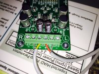
There is a voltage regulated 6.1 V supply to V analog part of Opus and a Salas 5V reg supply powering digital part of Opus . 5V(digital) from opus is also connected with a short wire to Cronus.
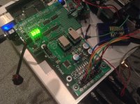
Hermes is not connected with any supply and getting powered from BBB, which has a 5V supply through DC socket.Please see pictures.
Please see the speaker wiring ,only used two bypass caps to the positive terminal.
Hermes is not connected with any supply and getting powered from BBB, which has a 5V supply through DC socket.Please see pictures.
Please see the speaker wiring ,only used two bypass caps to the positive terminal.
Attachments

Last edited:
It is not at 5 V,but 4.965V and that is the value without any load and with load connected.It can deliver up to 600 ma.
There is a voltage regulated 6.1 V supply to V analog part of Opus and a Salas 5V reg supply powering digital part of Opus . 5V(digital) from opus is also connected with a short wire to Cronus.
Hermes is not connected with any supply and getting powered from BBB, which has a 5V supply through DC socket.Please see pictures.
Please see the speaker wiring ,only used two bypass caps to the positive terminal.
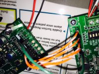
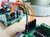
Kinku, I need a more closed-up view of wire connection at the Cronus output. Something funny as long as the photo shown here is concerned. Make a photo so as to clearly show the details of header pin alignemnt from L to R, i.e., LRCK to GND.
I was waiting to hear from you twluke.You are the only other one who is using Opus as far as I know. The difference between your pin and mine is you are using the outs in front of B3 connectors marked as B3SE. I am trying to get a good pic and post it in few min.
Twluke did your system work without any modifications?
Of course.
Hermes-Cronus-BBB with a single clock works well with the Opus. I've already checked this with my Opus Dacs. Of course, if the clock is 44.1k, it can not play 48k source and vice versa.is it because I have only one clock on board?
No need for grounding CS pin. Anyway wiring appears incorrect. You should wire in the same way as in B3SE. Refer to the photo shown here.I checked all wiring to opus multiple times. I am assuming the B3 connector has the MCK,BCK,D1,D2 at outer row of pins.
Do I need to ground the CS pin?
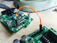
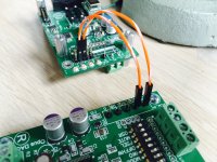
Green goes to DCK, Yellow to D1, Orange to D2 and Blue to GND with MCK as Red in front of Green. This connection of mine will help you. Your goal is not so far.
Attachments
Last edited:
I am going to put some pins in B3SE part and try there.But I thought B3 connector has the same pin outs
I am using same color connector for now so I made 4 shots ,starting with MCK--->MCK
DCK--->BCK
D1--->LRCK
D2 ---> DIN
G--->G
Do you think the B3SE connector is the way to go?
I am using same color connector for now so I made 4 shots ,starting with MCK--->MCK
DCK--->BCK
D1--->LRCK
D2 ---> DIN
G--->G
Do you think the B3SE connector is the way to go?
Attachments

I am going to put some pins in B3SE part and try there.But I thought B3 connector has the same pin outs
I am using same color connector for now so I made 4 shots ,starting with MCK--->MCK
DCK--->BCK
D1--->LRCK
D2 ---> DIN
G--->G
Do you think the B3SE connector is the way to go?
Kinku, you are playing with the wrong holes. Planned wire connection is correct but these are for B3 and you need the holes for B3SE which the Opus shares in the same way. Move all pins to the frontmost header nearly adjacent to u-Fl housing. Look at the signs and letters carefully. My last photo will help you.
kinku: wiring seems OK to me, at least from the pictures
can you measure DC voltages on them when playing something from BBB
for example use this command to generate 1kHz sinus @44100Hz at full volume (but disconnect amplifier/speakers!)
play -V3 -r 44100 -c 1 -b 32 -n -c 2 synth sin 1000 vol 0dB
command will print various info, but the last line should contain increasing time ... e.g.:
In:0.00% 00:00:05.94 [00:00:00.00] Out:280k [ | ] Clip:0
if above command fails after while (and time is not increasing) then BBB does not receive MCLK data
Planned wire connection is correct
I have to correct my statement. If the wiring to DI, D2, DCK and GND is correct, there is no difference between B3 and B3SE headers as miero implied. Sorry for confusion.
But if you tried each of B3 and B3SE wire connections and still get no sound, the culprit of your problem will include more wider possibilities, particularly basic soldering.
Last edited:
root@botic:~# play -V3 -r 44100 -c 1 -b 32 -n -c 2 synth sin 1000 vol 0dB
play: SoX v14.4.1
Input File : '' (null)
Channels : 1
Sample Rate : 44100
Precision : 32-bit
Endian Type : little
Reverse Nibbles: no
Reverse Bits : no
Output File : 'default' (alsa)
Channels : 2
Sample Rate : 44100
Precision : 32-bit
Sample Encoding: 32-bit Signed Integer PCM
Endian Type : little
Reverse Nibbles: no
Reverse Bits : no
play INFO vol: has no effect in this configuration
play INFO sox: effects chain: input 44100Hz 1 channels
play INFO sox: effects chain: synth 44100Hz 1 channels
play INFO sox: effects chain: channels 44100Hz 2 channels
play INFO sox: effects chain: output 44100Hz 2 channels
In:0.00% 00:01:42.35 [00:00:00.00] Out:4.51M [!=====|=====!] Hd:0.0 Clip:0
root@botic:~#
- Status
- Not open for further replies.
- Home
- More Vendors...
- Twisted Pear
- HermesBBB-Cronus-Opus