Hey Rick,
Excuse my ignorance, most of this is way over my head.
What exactly does this latest circuit do? To adjust temperature of the chip?
What do you mean by zero output offset ?
Excuse my ignorance, most of this is way over my head.
What exactly does this latest circuit do? To adjust temperature of the chip?
What do you mean by zero output offset ?
No need for excusing -- it's on me, I should've done some 'splainin'. 😀
As long as you have the 220uF non-polar capacitor between pin 7 and the headphones, this is Not Needed.
But there are folks hereabouts (and elsewhere 😉) that aren't too fond of capacitors in the signal path, especially inexpensive aluminum electrolytics! This is a way to eliminate that.
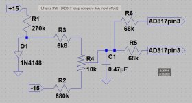
The designers of of the AD817 were expecting the surrounding circuitry to be low impedance -- achieving the gain and phase linearity for NTSC video requires it. The beginning of the offset trouble was choosing the 100k: The part has an input current in the 3uA range, and they are NPN transistors. Not terrible, but it means that the '+' input will rest at about -300mV with no signal. That's too much for headphones, thus J-P's solution using the 220uF to protect them.
So, just adjust the trimpot to minimize both AD817's offset at pin 7. Both devices won't come to 0 at exactly the same point. But it should be possible to get within a few millivolts, which is low enough to be OK. And it should be stable over about a 20°C range.
The diode is there to partially correct for the change in AD817 input current over temperature -- about 3,2uA a little below normal indoor room temp; ~2,7uA at the upper end of the range this circuit can correct.
Keep asking good questions!
Cheers
As long as you have the 220uF non-polar capacitor between pin 7 and the headphones, this is Not Needed.
But there are folks hereabouts (and elsewhere 😉) that aren't too fond of capacitors in the signal path, especially inexpensive aluminum electrolytics! This is a way to eliminate that.
The designers of of the AD817 were expecting the surrounding circuitry to be low impedance -- achieving the gain and phase linearity for NTSC video requires it. The beginning of the offset trouble was choosing the 100k: The part has an input current in the 3uA range, and they are NPN transistors. Not terrible, but it means that the '+' input will rest at about -300mV with no signal. That's too much for headphones, thus J-P's solution using the 220uF to protect them.
So, just adjust the trimpot to minimize both AD817's offset at pin 7. Both devices won't come to 0 at exactly the same point. But it should be possible to get within a few millivolts, which is low enough to be OK. And it should be stable over about a 20°C range.
The diode is there to partially correct for the change in AD817 input current over temperature -- about 3,2uA a little below normal indoor room temp; ~2,7uA at the upper end of the range this circuit can correct.
Keep asking good questions!
Cheers
Last edited:
Hey Rick,
Thanks for the explanation.
So this circuit connects to pin 7 of both ad817 chips.
Does the orginal +15v still connect at pin 7?
So now where would be a good place to put this circuit?
Also should I move the power supply for the headphones?
Hard to move forward without a good plan.
Thanks for the explanation.
So this circuit connects to pin 7 of both ad817 chips.
Does the orginal +15v still connect at pin 7?
So now where would be a good place to put this circuit?
Also should I move the power supply for the headphones?
Hard to move forward without a good plan.
Nope, nope, nope -- my bad. 😱 I gave the wrong pin # for the output pin: That phrase in the earlier post should read ".. AD817's offset at pin 6." That's where to measure the offset. Pin 7 still needs its +15V.
The best place to put it would be a little separate perfboard (potentially much more compact than Vero which forces orthogonal routing), reasonably close to the AD817s -- if possible close enough to 'share temperature'. The important thing to keep in mind about this little ditty is, it is specific to the AD817. Any of the op-amps better suited to this duty will not use it.
If you haven't already moved the power supply, save that for later. It probably should be done eventually, but 1) isn't likely to be the cause of the main current symptom, and 2) can't be evaluated for success until the offset problem has surrendered.
Are the 220uF non-polars in place on the outputs?
Ya know, perfboard is usually much cheaper than Vero board. If you use 1/4W resistors and a non-huge trimpot and capacitor, this little bit of circuit ought to fit easily on 2½ by 2½ cm of board. And be light enough to simply piggy-back over the AD817-area of the HPA, supported by its own connecting wires.
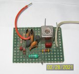
Below is a little VCO example from 30-some years ago, complete with dust and pet hair. It has more and larger parts, but about the same 9 nodes as your bias circuit. About 1 square inch.
Regards
The best place to put it would be a little separate perfboard (potentially much more compact than Vero which forces orthogonal routing), reasonably close to the AD817s -- if possible close enough to 'share temperature'. The important thing to keep in mind about this little ditty is, it is specific to the AD817. Any of the op-amps better suited to this duty will not use it.
If you haven't already moved the power supply, save that for later. It probably should be done eventually, but 1) isn't likely to be the cause of the main current symptom, and 2) can't be evaluated for success until the offset problem has surrendered.
Are the 220uF non-polars in place on the outputs?
Ya know, perfboard is usually much cheaper than Vero board. If you use 1/4W resistors and a non-huge trimpot and capacitor, this little bit of circuit ought to fit easily on 2½ by 2½ cm of board. And be light enough to simply piggy-back over the AD817-area of the HPA, supported by its own connecting wires.
Below is a little VCO example from 30-some years ago, complete with dust and pet hair. It has more and larger parts, but about the same 9 nodes as your bias circuit. About 1 square inch.
Regards
Last edited:
Hey Rick,
Ahh i see the circuit connects to the outputs.
Thanks for the tip on perf perf board. I don't see your picture.
I've only used veroboard so far. This is my third audio project.
So I'll have to learn how to use perf board. I recall watching a video about it a while back.
So I have an idea.
Any recommendations on brand or type and where to buy? I found that BusBoard Prototype Systems made good stripboard.
I haven't made any changes yet. I have to order parts first and figure the details.
Btw the muting circuit works perfectly. The sound of those relays firing is very satisfying.
It would be more standard and more efficient to start designing with a PCB program. Your devices will very likely perform better with a decent PCB.
gregas said:Ahh i see the circuit connects to the outputs.
Umm .. no, the 68k resistors are to provide the INPUT bias, and will alter the output quiescent voltage.
Sorry about the missing pics -- no doubt more *pilot error*. 😱
Big 'Yay' on the mute relays!😀
Cheers
Attachments
Last edited:
Thanks for the clarification. I'm going to put in an order. I don't have any 1/4w resistors. I've always purchased 1/2w. Any 10k potentiometer will work? I think i have some 5k ones.
JP perhaps on my next project I can try a pcb.
JP perhaps on my next project I can try a pcb.
If you're still doing or planning mostly valve work, staying with ½W as a 'house standard' might be a reasonable choice -- otherwise I don't see them much anymore. I didn't mean to suggest changing to 1/4W. The convenience of size is compelling for me, especially since the power levels rarely exceed a few milliwatts or 10's of 'em. And the leads plug into the proto-boards I have a lot better. Power supplies are the only place I fit bigger, as necessary.
Yes, any 10k pot will work fine.
Without re-doing the arithmetic (took me too long the first time), I'll guess there's a halfway decent chance the 'sweet spot' will be within range. If not, just add in a 4k7 on whichever end you need to move it (the sweet spot).
Regards
Yes, any 10k pot will work fine.
Without re-doing the arithmetic (took me too long the first time), I'll guess there's a halfway decent chance the 'sweet spot' will be within range. If not, just add in a 4k7 on whichever end you need to move it (the sweet spot).
Regards
Sorry -- the line, ".. just add in a 4k7 on whichever end you need to move it (the sweet spot)."
should instead read, ".. on the opposite end from the one where you're hitting the end stop."
😉
should instead read, ".. on the opposite end from the one where you're hitting the end stop."
😉
Hey Rick.
So I'm adding those 1/4w resistors to my order
Plus 4k7. Thanks.
https://www.mouser.ca/ProductDetail/652-3006P-1-103-LF/
How's this look for the trimpot?
So I'm adding those 1/4w resistors to my order
Plus 4k7. Thanks.
https://www.mouser.ca/ProductDetail/652-3006P-1-103-LF/
How's this look for the trimpot?
Those are pretty standard, and pretty decent. Wouldn't mind if they would pick a tempco sign, and not just specify +/-200ppm. Or a little better cycles/life (only "200" means you can't, as a practical matter, just keep a handful of these in your prototyping parts box and expect them to be reliable when you pull one out -- check/measure every use!)
If you get 10k trimpots, you shouldn't need the 4k7's. (Unless I booted the arithmetic .. 😱 !)
If you get 10k trimpots, you shouldn't need the 4k7's. (Unless I booted the arithmetic .. 😱 !)
How about this for the perfboard?
https://www.mouser.ca/ProductDetail/Twin-Industries/7100-45/?qs=TqtMe0HCz7dSS69HVnuJCg%3D%3D
Ok so no need for the 4k7 resistor
https://www.mouser.ca/ProductDetail/Twin-Industries/7100-45/?qs=TqtMe0HCz7dSS69HVnuJCg%3D%3D
Ok so no need for the 4k7 resistor
Yep, that looks just fine.
As long as you get 0,042" holes on 0,1" centers, and it's FR-4, you're getting pretty standard stuff.
As long as you get 0,042" holes on 0,1" centers, and it's FR-4, you're getting pretty standard stuff.
Rick,
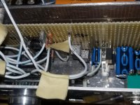
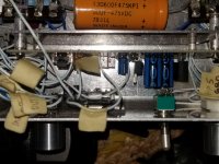
I've been thinking. I have that leftover veroboard that i removed all those components off with the mosfets. I could probably cut that to size and just use it instead of the perfboard. I don't think saving a bit of space is a big issue here, is it? I could also mount it to some stand off spacers mounted to the mounting screws for the headphone amp veroboard.
I've been thinking. I have that leftover veroboard that i removed all those components off with the mosfets. I could probably cut that to size and just use it instead of the perfboard. I don't think saving a bit of space is a big issue here, is it? I could also mount it to some stand off spacers mounted to the mounting screws for the headphone amp veroboard.
Attachments
Should be OK. But the ground lead from C1 on the bias circuit will need a short, direct (no service loop) connection, close to the pad between the bypass capacitors on the AD817 supply leads -- pins 4 and 7.
And if the bias circuit occupies somewhat less space, that's good thing.
Maybe don't worry about the mounting. Try to think of the little added circuit as a test assembly, instead of something permanent that needs to be properly secured.
Uhh .. one other thing I should probably mention: Sockets are not recommended for op-amps with bandwidth this high. Not sure what to suggest to change at this point in the project, though. Hopefully the rail bypass caps are close by.
Cheers
Hey Rick,
Thanks for the response.
I believe the sockets were used here's the ability to swap out chips.
Sounds like a major part of my problem is the chip that was chosen.
If the temp compens circuit works and I'm happy with the headphone amp, I would then find a way to mount it?
Thanks for the response.
I believe the sockets were used here's the ability to swap out chips.
Sounds like a major part of my problem is the chip that was chosen.
If the temp compens circuit works and I'm happy with the headphone amp, I would then find a way to mount it?
Yup! 😀
About the 'swap out chips' .. a lot of people have a lot of fun doing that. Trouble is, an op-amp is NOT an op-amp, is NOT an op-amp, etc ..
Not all flavors are directly interchangeable. Some of the times that someone complains about the exceedingly poor sound quality of an amp they subbed in, it's oscillating ultrasonically, or otherwise behaving poorly. And lacking an oscilloscope they have no idea(!), then they blame it on *fake* parts, or chalk it up to some other specious excuse. 😱
Cheers
Hey Guys,
I took a bit of a break from working on this HPA. I'm going to start back up on it. So i ordered parts and now have them for the modification to it. I'll be posting in a few days and let you guys know how it's going.
I took a bit of a break from working on this HPA. I'm going to start back up on it. So i ordered parts and now have them for the modification to it. I'll be posting in a few days and let you guys know how it's going.
Hey Rick,
So I've spent some time rereading the posts to bring me back up to speed.
I have a few questions.
In my original post R3 is 100k at the input, are we still going with that value?
also in your circuit in post # 67, D1 is 1N4148. Can i use IN4002 or UF4007? I have some extras of those types.
So I've spent some time rereading the posts to bring me back up to speed.
I have a few questions.
In my original post R3 is 100k at the input, are we still going with that value?
also in your circuit in post # 67, D1 is 1N4148. Can i use IN4002 or UF4007? I have some extras of those types.
Last edited:
- Home
- Amplifiers
- Headphone Systems
- help with op amp headphone amp hum and distortion