i'm not seeing anything getting hot.....
i do have 12v on pin 10 of the square transformer.
and 12v on each leg of q612.
i do have 12v on pin 10 of the square transformer.
and 12v on each leg of q612.
That's a problem. You should have ~0v on the third leg. ~13v on the center leg and ~0.7v on the first leg.
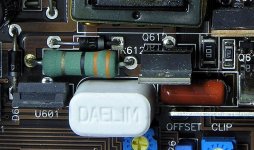
What are the markings on the large white resistor next to Q612?
What is the resistance across its terminals?
What are the markings on the large white resistor next to Q612?
What is the resistance across its terminals?
my amp doesn't have the resistor like that.....
i replaced the irfz34n, and it checked to be bad....
i have two resistors like the one in your photo that is laying down...
i replaced the irfz34n, and it checked to be bad....
i have two resistors like the one in your photo that is laying down...
Is there a green resistor standing up where the white resistor is in the photo?
If so, what are the colors on it and what's its value (measured with meter)?
If so, what are the colors on it and what's its value (measured with meter)?
It's open. It should be 0.30 ohms. It probably opened when the FET shorted.
Use only a flameproof or fusible resistor as a replacement.
Use only a flameproof or fusible resistor as a replacement.
got the resistor replaced, and checked the diodes around the square transformer....
now q612 gets so hot that it's going to self destruct......
joe
now q612 gets so hot that it's going to self destruct......
joe
There could be a couple of problems. The most likely is a shorted transformer. It may be difficult to check unless it's shorted from one set of windings to another.
Using the numbers from the earlier link...
1 should be shorted to 10
2, 3, 8 and 9 should be shorted together
4, 5, 6 and 7 should be shorted together
There should be no direct (0 ohm) connections between the 3 sets of windings above.
It's also possible that the transformer has a shorted turn in one of the 3 groups of windings above. You won't be able to determine if it does with an ohm meter.
Does the outside of the transformer show any signs of overheating?
transformer passes the ohm check......and it doesn't show any signs of heat.....also when q612 is the only thing that heats quickly....
i replaced the diodes around the transformer with 1n4007 as one of them was bad.......that's what i had laying around.
i replaced the diodes around the transformer with 1n4007 as one of them was bad.......that's what i had laying around.
Check the capacitors next to the diodes to see if any are shorted. If one is shorted, it's likely the one that is connected to the diode you replaced.
The 4007 isn't a high-speed diode and may run hot during normal operation. If you get the amp working, you should replace the 4007 with the same part number as the original.
Which diode was defective?
The 4007 isn't a high-speed diode and may run hot during normal operation. If you get the amp working, you should replace the 4007 with the same part number as the original.
Which diode was defective?
I would be surprised if it even function correctly at all with a 4007. You need a fast recovery diode.
Can you see any switching on Q612?
You should be able to measure frequency with a DMM.
With the diode you have in place the diode will be turned back on before it has time to turn off.
You should be able to measure frequency with a DMM.
With the diode you have in place the diode will be turned back on before it has time to turn off.
It's possible that the FET isn't being driven properly.
To see how your meter reacts to a high frequency signal, set it to AC and touch it to the third leg of any of the 4 power supply driver transistors (Q608-611). Be careful so you don't short the buss bar to the transistor with the meter probe.
Do it again on DC.
What does the meter read on each one?
If you do this on the first leg of Q612, what do you read?
The black meter lead should be on the ground terminal of the amp for each test.
- Status
- Not open for further replies.
- Home
- General Interest
- Car Audio
- help with my 500/1