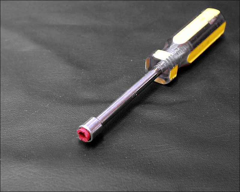
To reinstall them, I use the following 'tool'. The red insert is the insulation from 6g wire. It keeps the driver from sliding on the clamp. Tap them gently back into place.

Where you able to get new clips? I haven't bent any of mine but I haven't tried putting them back on yet either.shagone said:trial and error led me to this idea as well as a few bent up clips in the procces.
Hi Perry, thanks for all the help. Are you person who wrote the website in your link? I actually have one of those snap on tools. I found a screwdriver to be easier.
the ones that i bent originally before finding the tool that worked were easily bent or hammered back into shape and worked fine after re-installing them.
i have heard that new clips are nearly impossible to find. i have an amp or too here that arrived with a few missing clips if anyone has a lead on where to find them. one amp that comes to mind is an older Autotek that i need clips for.
i have heard that new clips are nearly impossible to find. i have an amp or too here that arrived with a few missing clips if anyone has a lead on where to find them. one amp that comes to mind is an older Autotek that i need clips for.
back to the soldering iron.....amp lasted for about 24 hours before she went up in smoke again......the amp when down right at the same time i started my truck.....i could hear the altenator whine through the speakers and then the dreadful pop, and shortly after that the smell......
q510 was destroyed ......i think it was a 2n3906.......replaced it and the ones on 501,503,509......
one of the 540's was cracked and replaced all four of those.......
replaced the diode that's mounted on heatsink......
here's the voltages on the10 pin plug near the power terminal block
pin1=.51 volts
pin2=0
pin3=12
pin4=9.5
pin5=11.5
pin6=12
pin7=0
pin8=.4
pin9=.5
pin10=0
i get a green light when i power it up.......but thats about it.....no output....
the 44's and the resistors appeared to be good.......at least the resistors are not burned up like it was the first time around....or teh 44's are not blown into.......
any ideas?
Measure the DC voltage on the gates of the IRFZ44s.
Measure the DC voltage on the pads of the output transistors. Do any have 80v DC?
Do the op-amps have ±15v on pins 4 and 8?
Make all measurements with the amp powered up. Monitor the temperature of the Z44s if they aren't clamped to the sink.
Did you find any problems when you disassembled the amp (transistor not seated properly against the sink, missing/damaged insulator, debris between transistor and sink, poor solder connection...)?
Q510 is a 2n3906. If I'm not mistaken, it's connected in parallel with the one next to it. Both must be replaced if one failed.
Measure the DC voltage on the gates of the IRFZ44s......I'm seeing about 265mv....
Measure the DC voltage on the pads of the output transistors. Do any have 80v DC?.......none
Do the op-amps have ±15v on pins 4 and 8?.......i'm not sure what you mean????
Make all measurements with the amp powered up. Monitor the temperature of the Z44s if they aren't clamped to the sink........it's powered by positive, negative, and the remote wire........and that's all..........
Did you find any problems when you disassembled the amp (transistor not seated properly against the sink, missing/damaged insulator, debris between transistor and sink, poor solder connection...)?........everything looked good.....
Q510 is a 2n3906. If I'm not mistaken, it's connected in parallel with the one next to it. Both must be replaced if one failed.........yes it's paralleled with another one and both were replaced.............
joe
I was trying to determine if the supplies were operating. If you don't have voltage on the outputs, the main supply is not operating. This is the supply driven by the Z44s. Check the voltage approximately 5 seconds after the remote voltage is applied. If I'm not mistaken, the drive signal on some of these amps will switch off if there is a problem. At 5 seconds, the signal should be present on the gates. Also check the voltage on the center leg of the FETs. They should be at B+.
The 8 pin op-amps will have +15v on pin 8 and -15v on pin 4. The 14 pin op-amps will have +15v on pin 4 and -15v on pin 11. If they don't have voltage, the low voltage supply isn't operating.
Do you have an oscilloscope?
The 8 pin op-amps will have +15v on pin 8 and -15v on pin 4. The 14 pin op-amps will have +15v on pin 4 and -15v on pin 11. If they don't have voltage, the low voltage supply isn't operating.
Do you have an oscilloscope?
no i don't have a scope, not yet........i have noticed that after 5 seconds the green light turns off......and i don't have the preamp output from the cd hooked up.....
ok i checked all the center legs of the 44's (drain) and i have 12vdc.....
where is the 8 or 15 pin op amps located........i guess i need to check it as well........
joe
ok i checked all the center legs of the 44's (drain) and i have 12vdc.....
where is the 8 or 15 pin op amps located........i guess i need to check it as well........
joe
yeah the green light kicks off after 5 seconds, i guess because i don't have any drive signal..........do i need to apply a signal to test....
joe
joe
Switch the signal sensing off and use the remote to turn the amp on/off.
This is the datsheet for the op-amps marked 2068. Look at the pin configuration drawing so you can find pins 4 and 8.
http://bcae1.com/temp/NJM2068_E.pdf
This is the datsheet for the op-amps marked 2068. Look at the pin configuration drawing so you can find pins 4 and 8.
http://bcae1.com/temp/NJM2068_E.pdf
signal sensing is off, and the green light goes off after 5 seconds...........no voltage on the 8 pin op-amps marked 2068..
Something's shutting down the amp. Measure the DC voltage on the 10 pin connector. Measure them when the green light is on and when the green light is off.
LED ON
Pin 1:
Pin 2:
Pin 3:
Pin 4:
Pin 5:
Pin 6:
Pin 7:
Pin 8:
Pin 9:
Pin 10:
LED OFF
Pin 1:
Pin 2:
Pin 3:
Pin 4:
Pin 5:
Pin 6:
Pin 7:
Pin 8:
Pin 9:
Pin 10:
Also measure the DC voltage across the two center speaker terminals. Touch the meter to the speaker terminals and THEN apply remote. Leave them there until the LED goes off. How high does the voltage go?
LED ON
Pin 1: 5
Pin 2: 0
Pin 3: 12
Pin 4: 9
Pin 5: 12
Pin 6: 12
Pin 7: .65
Pin 8: 11
Pin 9: 11
Pin 10: 0
LED OFF
Pin 1: 0
Pin 2: 0
Pin 3: 12
Pin 4: 9
Pin 5: 12
Pin 6: 12
Pin 7: .65
Pin 8: .5
Pin 9: 11 and about 10 seconds it drops to .5
Pin 10: 0
Also measure the DC voltage across the two center speaker terminals. Touch the meter to the speaker terminals and THEN apply remote. Leave them there until the LED goes off. How high does the voltage go? 62vdc and starts to drop after the light goes out.....
joe
The amp appears to be shutting down from DC offset. This could be due to a fault in the output stage or from a power supply fault.
You should have had -15v on pin 2 of the 10 pin connector but it switches on at ~5 seconds after remote is applied so it's not clear whether you'd see it on your amp. Recheck the voltage on the 2068 op-amps (just a few of them). Confirm that you have both positive (pin 8) and negative (pin 4) voltage on them.
If the voltage is present, remove the output transistors to see if it will remain on without them. Before applying power, be absolutely sure that there are no solder bridges between the pads of the output transistors.
ok i'm seeing about 83vdc on the drains of the outer two of the outputs....nothing on the inner two.....
i don't have -15v on pin 2 of the 10 pin connector...
rechecked couple of the 2068 op-amps , i have some (not much) positive voltage, but nothing negative.
i looked very close and there's no solder bridges.
what are q608, q609, q610, q611? are they drivers for the 44n's?
i'm seeing different readings between the four........hard to see the part numbers....
Is the amp staying on for more than 5 seconds now?
When you measured the voltage on pins 4 and 8 of the op-amps, precisely how much voltage did you have?
Those transistors drive the Z44s. If you have rail voltage, they're likely OK.
What's the revision number on your amp?
When you measured the voltage on pins 4 and 8 of the op-amps, precisely how much voltage did you have?
Those transistors drive the Z44s. If you have rail voltage, they're likely OK.
What's the revision number on your amp?
no, the amp is still shutting off after a few seconds.......
pin 4 i'm seeing .665 vdc
pin 8 i'm seeing 2.8 vdc
pcb 100006 rev. 11
pin 4 i'm seeing .665 vdc
pin 8 i'm seeing 2.8 vdc
pcb 100006 rev. 11
Thats odd q608, q609, q610, q611 are the drivers to the fets they should all be the same.
Seems odd your seeing 80V but not seeing any voltage on the opamps. Does anything get hot? Obviously be careful what you touch if you have 80v!!!!!!!!
You should have +15v on pin 8 and -15v on pin4. Either the suppy to this circuit is not turning on or something is pulling it down.
Seems odd your seeing 80V but not seeing any voltage on the opamps. Does anything get hot? Obviously be careful what you touch if you have 80v!!!!!!!!
You should have +15v on pin 8 and -15v on pin4. Either the suppy to this circuit is not turning on or something is pulling it down.
Two of the PS drivers are connected to 12v. Two are connected to ground. The signals on the bases and emitters should essentially be the same if they're working properly,
The 80v is produced by the Z44s and the large transformer. The low voltage for the op-amps is produced by the small, square yellow transformer near the center of the board.
Do you have 12v on pin 10 of the square transformer? Refer to the following file for pin numbering:
http://bcae1.com/temp/jl500slashonelowvtransformer.swf
Post the DC voltage you have on each leg of Q612.
- Status
- Not open for further replies.
- Home
- General Interest
- Car Audio
- help with my 500/1