I don't see how they could cause it to get hot. Worst case, the supply would operate but the diodes would run hot.
If they're really slow, they could possibly make the filter caps run hot but that's unlikely.
If they're really slow, they could possibly make the filter caps run hot but that's unlikely.
i don't see any difference with my meter on ac with q608-611.....
on q612
source=0vdc
drain=12vdc
gate=4.5vdc
about 2 seconds and q612 gets hot enough to burn you.....
it didn't start getting hot until i replaced the flameproof resistor..
on q612
source=0vdc
drain=12vdc
gate=4.5vdc
about 2 seconds and q612 gets hot enough to burn you.....
it didn't start getting hot until i replaced the flameproof resistor..
I need both AC and DC on the third leg of one of the drivers AND both AC and DC on Q612.
PS driver leg 3 AC:
PS driver leg 3 DC:
Q612 gate AC:
Q612 gate DC:
Q612 drain AC:
Q612 drain DC:
Q612 source AC:
Q612 source DC:
Q612 couldn't get hot before you replaced the resistor because it's connection to ground was broken.
PS driver leg 3 AC:
PS driver leg 3 DC:
Q612 gate AC:
Q612 gate DC:
Q612 drain AC:
Q612 drain DC:
Q612 source AC:
Q612 source DC:
Q612 couldn't get hot before you replaced the resistor because it's connection to ground was broken.
I need both AC and DC on the third leg of one of the drivers AND both AC and DC on Q612.
PS driver leg 3 AC:.....fluctuates high as .716
PS driver leg 3 DC:..... .78
Q612 gate AC: fluctuates under 1volt
Q612 gate DC: 4.5v
Q612 drain AC: fluctuates under 1volt
Q612 drain DC: 12v
Q612 source AC: fluctuates high as .8
Q612 source DC: 0
Q612 couldn't get hot before you replaced the resistor because it's connection to ground was broken.
my DMM might not be what i need for measuring ac......
The meter isn't telling me much. The fact that it read AC voltage when on ground shows the readings are unreliable.
There is a short in the Q612 circuit but the circuit is large. Virtually all of the op-amps and the filter caps are on the output of the circuit. The other side of the circuit includes the driver IC. Right now, I'm trying to determine if you have pulses on the gate or straight DC. DC would make the transistor get really hot. The meter can read 4.5v DC for pulsed DC (which would be OK) or straight DC (which would be bad).
To determine if you have straight or pulsed DC, you need to build the following circuit. One end will go on the gate of Q612 and the other end will go on the source of Q612. If the LEDs light, you have a good drive signal. If it blinks and then goes off, you have straight DC.
The capacitor is a 0.1uf. The resistor is a 1k. Notice that the LEDS are wired in reverse parallel.
http://bcae1.com/temp/IMG_5686oscdetector.jpg
i'm seeing 80vdc on 3 of the 4 output drains...... no +- 15 on the opamps pin 4 and 8..
parts that failed.......q510, q509, q612, and r613. that i know of
i have 12vdc on pins 1 and 2 of the small transformer...
parts that failed.......q510, q509, q612, and r613. that i know of
i have 12vdc on pins 1 and 2 of the small transformer...
You should only have 80v DC on 2 of the drains.
The fact that you don't have all of the proper driver power supplies operating may explain why you have 3 with 80v.
I don't know what 613 does.
12v DC on pins 1 and 10 is normal.
The fact that you don't have all of the proper driver power supplies operating may explain why you have 3 with 80v.
I don't know what 613 does.
12v DC on pins 1 and 10 is normal.
ok i got the old magnifying glass out and found a burnt resistor under the preamp board........it reads around 47 ohms across it........the input power reads like a short and then it starts to climb to a high resistance........none the capacitors are shorted.......
Attachments
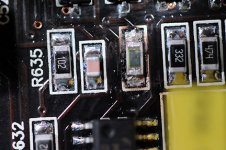
If one end is connected to the gate of the FET and the other end is connected to pin 6 of the IC next to it (UC3843B?), it's a 47 ohm resistor. It burned when the 3843 tried to drive the defective FET. They are generally 47 ohms.
What's the REV # on the main board? I thought it was a 3 but the photos I have of a 3 are different.
What's the REV # on the main board? I thought it was a 3 but the photos I have of a 3 are different.
- Status
- Not open for further replies.
- Home
- General Interest
- Car Audio
- help with my 500/1