Hans & Marcel,
I really respect and appreciate your discussion as an aim to get to an optimum for "my" project. Not wanting to incompetently interfere, though, I'll just say that I am planning on 1% Caps and maybe 0.1% Rs, so the actual performance hopefully nears the simulations. So far as I understand, I seem to need a well balanced Output more than differential one for my DAC to Box interconnect. The trade offs of optimising for balanced or differential are not sufficiently clear to me yet to make an informed decision, but it seems that the differential route would be the one with less distortion. Having said that, about which level of subjective sound quality differences are talking about in the one or the other case? As you hopefully see, I'm up for a good, pragmatic solution.
Thanks and Greetings,
Winfried
Hans, whether common mode filtering is necessary depends on a lot of things I have no information about, like how big the common mode and differential spikes are that come out of the DAC, what the exact behaviour of the amplifiers is, what the distortion requirements are. In this specific case, the whole discussion is rather academic as the transimpedance stage that has to handle the worst spikes is given.
Winfried, I think you got several suggested circuits that are all likely to work well. Either pick one at random or try several and see if you can detect any differences.
Repeating a question from a few posts back: does anyone know if the AD1853 has digital correction for analogue filter roll-off, like the Philips designs used to have?
Repeating a question from a few posts back: does anyone know if the AD1853 has digital correction for analogue filter roll-off, like the Philips designs used to have?
Marcel, that was exactly my point because the questioned caps are behind the I/V converters, these have to deal with CM spikes in the frontline.Hans, whether common mode filtering is necessary depends on a lot of things I have no information about, like how big the common mode and differential spikes are that come out of the DAC, what the exact behaviour of the amplifiers is, what the distortion requirements are. In this specific case, the whole discussion is rather academic as the transimpedance stage that has to handle the worst spikes is given.
And just as a sidenote, I never asked Winfried anything about non diff outputs with bal impedances 🤣
Hans
I fully support your DIY efforts aiming for perfection and possibly improved sound.Hans & Marcel,
I really respect and appreciate your discussion as an aim to get to an optimum for "my" project. Not wanting to incompetently interfere, though, I'll just say that I am planning on 1% Caps and maybe 0.1% Rs, so the actual performance hopefully nears the simulations. So far as I understand, I seem to need a well balanced Output more than differential one for my DAC to Box interconnect. The trade offs of optimising for balanced or differential are not sufficiently clear to me yet to make an informed decision, but it seems that the differential route would be the one with less distortion. Having said that, about which level of subjective sound quality differences are talking about in the one or the other case? As you hopefully see, I'm up for a good, pragmatic solution.
Thanks and Greetings,
Winfried
It gives a lot of satisfaction of having brought a project successfully to an end.
Good that you want to use 1% caps, and tight tolerance resistances on critical positions, that will make a difference.
Hans
In that case I would borrow one of the many working examples that abound the internet. At the very least it would show what a working design looks like.I'm up for a good, pragmatic solution.
@rfbrwIn that case I would borrow one of the many working examples that abound the internet. At the very least it would show what a working design looks like.
Thanks for the hint at an alternative! It would help me a lot, though, if you could/would post some kind of a starting point for me like a link or the search terms to use. The DAC chip AD1853 as DAC output of the DEQX PDC DSP part is what I have as interface. So what to search for as "working examples that abound" I just don't know. The "Internet" is huge, searching/finding can be hard....
Regards,
Winfried
@rfbrw
well, searches for AD1853 DAC schematics and products made it obvious (as expected), that the chip has a good reputation, was used in many great products, but it is long outdated. So products which I could use instead of my own board not available and schematics I found were based on the app notes from AD, just as mine, but there seems to be no balanced output version...
Maybe you wanted to hint at something else and I misunderstood you?
Greetings,
Winfried
Last edited:
Winfried,@rfbrw
well, searches for AD1853 DAC schematics and products made it obvious (as expected), that the chip has a good reputation, was used in many great products, but it is long outdated. So products which I could use instead of my own board not available and schematics I found were based on the app notes from AD, just as mine, but there seems to be no balanced output version...
Maybe you wanted to hint at something else and I misunderstood you?
Greetings,
Winfried
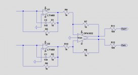
When looking for comparable circuit diagrams as what you have in mind, here is the differential/balanced version of my Bel Canto 3.5VB D/A converter.
Instead of a AD1853 it is using a PCM1792, both Dac's having current outputs.
This Bel Canto was a rather expensive D/A converter that I got for free because I gave some valuable feedback on their previous design.
As you can see, Bel Canto did not even use a filter around the OPA1632 and all filtering was done by the Dac's OS filter and the I/V converters with their 6db/oct slope.
In your case, you even have a 12dB/oct filter around the I/V converters (C46/C47 + C57), so you could also completely leave the filters around the OPA1632.
What we have seen in another thread comparing NOS Dac's to OS Dacs, was that we could not find any evidence that the HF content of a NOS Dac was noticeable, but that the length of the OS filter played an important role and short filters seemed to worsen sound perception.
These tests should be seen as a clear indication, but not as conclusive given the amount of people, but Bel Canto's decision to filter as little as possible can be fully understood.
So as a test, you could try exactly the same, with and without any filtering filter around the OPA1632.
This will also completely push the CMRR question to the background.
Hans
Attachments
Hello Hans,
thanks for posting such a constructive comment, much appreciated!
Well, taking your remarks into consideration, my layout could go to production as and I could then build up differently populated boards. This way I may end up with a few unused or shoted components, but that's OK with me!
Caveats are:
I'm building this for a (new) active three way, so testing different 3-way board options does not seem viable...
I could build three differently populated boards, each according to a different alternative described above and compare these with my current, but by far not excellent passive speakers.
I will at some point need assistance with what / how to measure and compare board performance to support the final version decision
Regards,
Winfried
HHm, the difference for magnitude and phase looks almost negligible to me. The 2nd pole of the input filter is way up, btw, making it basically 1st order.As you can see, Bel Canto did not even use a filter around the OPA1632 and all filtering was done by the Dac's OS filter and the I/V converters with their 6db/oct slope.
In your case, you even have a 12dB/oct filter around the I/V converters (C46/C47 + C57), so you could also completely leave the filters around the OPA1632.
What we have seen in another thread comparing NOS Dac's to OS Dacs, was that we could not find any evidence that the HF content of a NOS Dac was noticeable, but that the length of the OS filter played an important role and short filters seemed to worsen sound perception.
These tests should be seen as a clear indication, but not as conclusive given the amount of people, but Bel Canto's decision to filter as little as possible can be fully understood.
--------------
@wgh52, I suggest you keep all the option in the layout for various cap arrangement etc.
I'd add series resistance (like 3.3R) to the board's supply input. The 1632 is a 180MHz OpAmp, we don't want to have any ringing (== high impedance) on the supply which easily happens with a cable connect to the main board (C-L-C tank circuit). EDIT I see now you have 100R here, maybe a bit large...
I haven't checked the layout thoroughly but one thing stroke my eye: The GND sides of the 100nF decoupling caps should not use seperated vias to connect to the GND, rather they should join first and then go to the plane at one single point (which may consist of multiple vias), and in this case the plane does not even connect these via points directly.
Now because of the balanced output this is all much less of a problem as no signal content actually is referred to GND, only the common-mode part is. Plus your layout would work fine quite probably.
Anyway, I again might suggest a 4-layer board which makes life so much easier, see my proposal sketch here:
Last edited:
HHm, the difference for magnitude and phase looks almost negligible to me. The 2nd pole of the input filter is way up, btw, making it basically 1st order.
@wgh52, I suggest you keep all the option in the layout for various cap arrangement etc.
I'd add series resistance (like 3.3R) to the board's supply input. The 1632 is a 180MHz OpAmp, we don't want to have any ringing (== high impedance) on the supply which easily happens with a cable connect to the main board (C-L-C tank circuit). EDIT I see now you have 100R here, maybe a bit large...
I haven't checked the layout thoroughly but one thing stroke my eye: The GND sides of the 100nF decoupling caps should not use seperated vias to connect to the GND, rather they should join first and then go to the plane at one single point (which may consist of multiple vias), and in this case the plane does not even connect these via points directly.
Now because of the balanced output this is all much less of a problem as no signal content actually is referred to GND, only the common-mode part is. Plus your layout would work fine quite probably.
Anyway, I again might suggest a 4-layer board which makes life so much easier, see my proposal sketch here
What affordable 4 layer PCB design program could you suggest , I would be most interested because the ones I know are far from being cheap.
Regarding your comment on the input filter, you are right when you looked at Analog's suggested components, 2*220pF + 330pF.
In the sim I did, I used 2*500pF + 10nF giving a second order filter, just because we don't know what the cap values are in Winfried's system.
But it doesn't have to be a second order filter to filter the HF images as Bel Canto shows.
Images are probably at multiples of 8*192Khz with the multibit ƩΔ
That also questioned the need to filter around the OPA1632 with those numerous suggested caps.
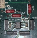
I have added a picture made from the Bel Canto PCB showing its layout. Between both outputs there is still an RC network visible, R=100R, C=unknown.
Hans
Attachments
What affordable 4 layer PCB design program could you suggest...
Kicad 6 is out.
Thx Mark,Kicad 6 is out.
I’m going to try it, looks very promising.
Hans
Regarding your comment on the input filter, you are right when you looked at Analog's suggested components, 2*220pF + 330pF.
In the sim I did, I used 2*500pF + 10nF giving a second order filter, just because we don't know what the cap values are in Winfried's system.
But it doesn't have to be a second order filter to filter the HF images as Bel Canto shows.
Images are probably at multiples of 8*192Khz with the multibit ƩΔ
That also questioned the need to filter around the OPA1632 with those numerous suggested caps.
You can't be sure, but chances are that the filter is close to the recommended circuit from Analog Devices. The team that came up with the recommended circuit knew the AD1853 better than anyone and must have spent quite some time optimizing it.
A very large capacitor between the virtual ground nodes will increase noise gain and reduce loop gain. Are the noise and distortion performance still reasonable with 10 nF?
Good questions, I didn't inspect those additional parameters, just created a second order filter because cap values were unknown.You can't be sure, but chances are that the filter is close to the recommended circuit from Analog Devices. The team that came up with the recommended circuit knew the AD1853 better than anyone and must have spent quite some time optimizing it.
A very large capacitor between the virtual ground nodes will increase noise gain and reduce loop gain. Are the noise and distortion performance still reasonable with 10 nF?
So let's assume Winfried has the recommended AD values.
As mentioned, a first order filter will perfectly do the job.
Hans
Sometimes listening tests suggest dacs sound better with less opamps in the signal path. The tradeoff in that case may be less filtering. Seemingly low-ish level clock-edge noise can still exist at measurable levels at frequencies far beyond the 10MHz shown earlier in this thread. How particular downstream equipment may respond to remaining HF noise is not always known. For example, some amplifiers are not well filtered at the inputs...
Last edited:
Diptrace also allows 4 layers in free mode. Or rather, it allows 2 signal layers and as many planes as you want; so have your 2 signals layers, plus a ground and power plane, or 2 ground planes. You can also apply for a free hobbyist license for Fusion360, which gives you eagle as part of that package. You need a reasonable computer to make use of that though, but having modelling, schematic, layout and some simulation in the one package is pretty neat indeed.
Once you have a ground plane, it really becomes a whole lot easier. for decoupling I would then generally use many vias (as many as feasible) in parallel on the ground side of the caps, or make small islands around each VEE/VCC and then stitch them to GND with multiple vias. this becomes a case of getting free performance upgrades with no parts and no additional cost, due to the low inductance.
regarding filtering; indeed, sometimes less is more, or at least sometimes more is not required. In discrete designs sometimes you can leave that filtering up to the gate capacitance of a fet. With ESS I have found no measurable benefit to additional input filtering in those cases. Totally agree with leaving placement for them to fit if required. if not required, dont fit them.
How good to know all those alternative PCB design programs, thank you.Diptrace also allows 4 layers in free mode. Or rather, it allows 2 signal layers and as many planes as you want; so have your 2 signals layers, plus a ground and power plane, or 2 ground planes. You can also apply for a free hobbyist license for Fusion360, which gives you eagle as part of that package. You need a reasonable computer to make use of that though, but having modelling, schematic, layout and some simulation in the one package is pretty neat indeed.
Once you have a ground plane, it really becomes a whole lot easier. for decoupling I would then generally use many vias (as many as feasible) in parallel on the ground side of the caps, or make small islands around each VEE/VCC and then stitch them to GND with multiple vias. this becomes a case of getting free performance upgrades with no parts and no additional cost, due to the low inductance.
regarding filtering; indeed, sometimes less is more, or at least sometimes more is not required. In discrete designs sometimes you can leave that filtering up to the gate capacitance of a fet. With ESS I have found no measurable benefit to additional input filtering in those cases. Totally agree with leaving placement for them to fit if required. if not required, dont fit them.
So far I was using Target3001, restricted to 2 layers and 400 pins max.
Upgrading to a 4 layer version with 1200 pins max costs ca. 835,- Euro, not very inviting to do for just a hobby.
Hans
- Home
- Source & Line
- Digital Line Level
- Help requested: DAC I>V conversion, filter, balanced buffer