For the circuit in #80, the time constants C1, R23 & C5, R29 are to close to each other. If NFB were used there is danger of LF instability. For a long tailed phase invertor the relation Rk ( mu +1 ) >> rp + Rl must be satisfied. This one barely makes it, but R21 has been made slightly larger to help that. A CC in the tail would be a better fix. There is no cap between the input jack & the first grid. A drop of 25V across only half of the OPT winding with a plate current of 50 mA indicates 500R. That is very large, eeven a low cost replacement OPT would do better.
All these points make me wonder if the circuit was ever built.
All these points make me wonder if the circuit was ever built.
Sent a PM.I'm in the UK too so I know the cheap tube choices. First on the list would be 6C4C, the Russian 6B4G. These are Svetlana, and great quality and build. This was modelled on the RCA 2a3. These are the tubes I use in my SE amp in preference to 300b. Expect to pay around £30 each from Russia or the Ukraine. I bought a dozen or so for all my projects. They also sound marvellous as a preamp tube, so that's an added benefit.
Second choice would be EL38. I have plenty if you PM me - I'm in London. I spent all of 2020 building prototype SE amps with pentode tubes in triode, and EL38 was easily the best sounding. I have a few different types including some rare ones. These have a top cap if that's OK.
Third choice, again from my 2020 experiments, was the EL12 which was second only to the EL38. Hot tip is the EL12n which has no top cap and is available new from a few European dealers. Again, I have stocks of unused ones including a matched quad. These are good value tubes. I also have several of the regular EL12 and EL12 Spez.
Since the EL38 and EL12 have a gain of around 15 in triode, this simplifies the driver stage a lot. You can use a simple 6SN7 for instance. In fact you can use a DHT stage like a 26, 4P1L, 2P29L or even 46, 47 or 10Y. That's what I was doing since I have stocks of all these. Sounded great! What I called the "inverted DHT amp" with the DHT on the input where actually it has more influence on the sound.
My final choice was to use 6C4C outputs, but the EL38 or EL12 with DHT input was running it pretty close.
I
I've had something similar running on & off the bench for about a year. An honest 7W at clipping in Class A PP without exceeding plate dissipation. The 6EM7 dissimilar triode has about the same plate dissipation as the 6AV5. But includes another high mu triode for a voltage amplifier. Connected as a differential stage here with a 120K tail to -150V, results in a very good phase splitter. Still needs a front end. The spectrum shews SMPTE Intermediation Distortion at 3W,Check out keggers 6AV5 PP triode amp over at Audiokarma.
https://audiokarma.org/forums/index.php?threads/diy-6av5-amplifier-want-to-build-one-or-two.309374/
Attachments
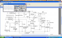
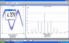
Got any distortion measurements?I use 6AV5 in one of my modular amp designs... I get about 25W in AB1 from a pair using 320V B+ into 2k2 Ra-a. Yes, I exceed the datasheet max Pd but the tubes don't give a crap at all.
Here's my front end etc.
That design is 12 Watts at best.A pair of 6080's using cathode bias on each tube is good for 25W.
Um no. not 30W. However it is a decent amplifier considering when it was designed. No way you get 30W out of 2a3 P-P. Nope.30W with PP 2A3, the Brook 10C
How so? It just measured 20W on the bench today.That design is 12 Watts at best.
Perhaps you know something the rest of us don't.
Shew us your proof, with a captioned schematic.
And some real calculations.
Well, you can, and the Brook did, with CF drivers and sliding auto-bias.Um no. not 30W. However it is a decent amplifier considering when it was designed. No way you get 30W out of 2a3 P-P. Nope.
https://www.tubecad.com/2007/12/15/High-Quality Audio Amplifier With Automatic Bias Control.pdf
I have gravitated towards this circuit to base the amplifier on. I have a couple of signal transformers that ought to work for the input phase splitter.
View attachment 1019535
http://www.tube-amps.net/EA_Hashimoto_EL34_PP_NNFB_02.htm
I have similar enough iron, and some 12BH7s etc. I have the intention of making "tube rolling friendly" for the small tube (adjustable current source for the input differential pair?), and probably fixed bias for the output tubes.
Here is a 20wpc triode EL34 amp that is extremely easy to build. I'm lucky to have the LS-57 outputs, but a high-quality 5K p-p transformer should work as well. You might have to back off the feedback a bit. I've built a number of Williamson amplifiers and this is one the best-sounding to date. A really lovely amplifier. I used the stock Heathkit Williamson design he indicates in the vid, but did a little tweaking to the shelf filter and feedback values for stability and smoother response. Oh, and that's not me in the video, I just copied the design. ;-)
Last edited:

Shelf Filter?
Did you mean the dominant high frequency pole, series RC from a plate to ground,
or alternatively, a series RC across the plate load resistor?
Thanks!
Did you mean the dominant high frequency pole, series RC from a plate to ground,
or alternatively, a series RC across the plate load resistor?
Thanks!
Shelf Filter?
Did you mean the dominant high frequency pole, series RC from a plate to ground,
or alternatively, a series RC across the plate load resistor?
Thanks!
Yes, the low-pass filter, some people call it a high-frequency shelf network, across the plate resistor of the input tube to limit the ultrasonic HF response. They became pretty much standard in Williamson amps after it was found they were prone to oscillate due to the extended HF response.
Last edited:
I believe . . .
The purpose of the dominant pole in an amplifier that has global negative feedback, is to make the total amplifier gain go to unity at a high frequency, before the output phase at that frequency becomes 180 degrees.
Because when the negative feedback loop shifts by 180 degrees, it becomes positive feedback.
Positive feedback, and gain more than unity . . . makes the amplifier an oscillator.
Often the fastest changing high frequency phase shift in an amplifier is the phase shift from the output transformer primary to the secondary (2 pole low pass filter). 12dB/octave
Often, the output transformer is also a high pass filter to low bass frequencies (1 pole high pass filter). 6 dB/octave
Build an amplifier, you may get an oscillator.
Build an oscillator, you may get an amplifier.
That happens more often than you think!
Just my opinions
Last edited:
I believe . . .
The purpose of the dominant pole in an amplifier that has global negative feedback, is to make the total amplifier gain go to unity at a high frequency, before the output phase at that frequency becomes 180 degrees.
Because when the negative feedback loop shifts by 180 degrees, it becomes positive feedback.
Positive feedback, and gain more than unity . . . makes the amplifier an oscillator.
Often the fastest changing high frequency phase shift in an amplifier is the phase shift from the output transformer primary to the secondary (2 pole low pass filter). 12dB/octave
Often, the output transformer is also a high pass filter to low bass frequencies (1 pole high pass filter). 6 dB/octave
Build an amplifier, you may get an oscillator.
Build an oscillator, you may get an amplifier.
That happens more often than you think!
Just my opinions
Yes, I understand, thanks. My point was that the amp, as built in the video, was unstable and wouldn't tolerate any capacitance across a fixed load. I swapped in a more aggressive shelf filter and did some tuning to make it very stable.
In any event, it's a lovely amp and capable of 18-20 watts. Since the OP was shifting his thinking to a triode-wired EL34 amp I thought I mention this classic Williamson approach--relatively simple and with a very natural tone. I have not tried any other output transformers with it. Possibly a consultation with Jack Eliano at Electraprint would result in an affordable alternative that would tolerate the amount of feedback used.
Do any of the circuits offered satisfy the original requirement?I have single ended triode and pentode amps and push pull pentodes, so got to thinking about building a push pull triode amplifier.
Target output: 15 - 20 watts no feedback.
Ideally something just a little bit more exotic than trioded el34, 84 6L6 etc.... and got plans for PL36s EL500/4/9 already so not them. UK based which seems to limit the (cheap) availability of a lot of American triode sweep tubes that would be suitable. 🙁
Don't want to spend much money if possible.
Seems the days of super cheap tubes are gone, initial thoughts, in an ideal world, would be something like a 2A3 amp, but even 6B4G quite expensive nowadays.
Initially the 6P21s seems like it could provide some DHT goodness, but I hear reservations about the longevity of the filament. It is a "relatively normal" tube though? so if that was a problem it would not be a total loss to redesign the amp with say a 6L6 type of valve. I could use a fairly normal 6k ish A-A output transformer.
I also have some 12E1 tubes. I get the impression they are not the happiest in triode mode though, but they are more powerful than I need so some room for flexibility, but seems moving towards lower voltage lower Z transformer.
And then there are the (Russian) regulator triodes, and 6080s. On reflection I could imagine paralleled 6080s (2) into a carefully chosen toroidal mains transformer, although not aesthetically what I am after, could have the potential to deliver the kind of sound I think I would like, clean and tight...
any thoughts.
To the point where it would be built? Which circuit(s) do you favor & why?
And will we see some photos, schematics & test results.
Just curious, many of these threads seem to simply die.
Hi. Pregnant pause at the moment. Have order some, ehem, Lundahl 1679s. Not really cheep anymore, but I sold some stuff and had a bit of extra cash. Also they are relatively more huge than I had allowed for in the original design, so have stopped building as I will work out where everything will fit, when they turn up... Hope they turn up. Was supposed to be 2 weeks, but nothing as yet.
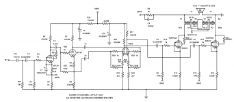
I am building the the circuit in post 72, as it is a little un usual with a transformer input, and promises low distortion. I have enjoyed all the other circuits, and quite like the idea of the non symmetric triode amp, and introduced me to some other nice valves, like the CV6040, which is a 12E1 in a smaller bottle.
I am building the the circuit in post 72, as it is a little un usual with a transformer input, and promises low distortion. I have enjoyed all the other circuits, and quite like the idea of the non symmetric triode amp, and introduced me to some other nice valves, like the CV6040, which is a 12E1 in a smaller bottle.
- Home
- Amplifiers
- Tubes / Valves
- Help deciding on a low cost 15-20 watt triode push-pull amplifier design