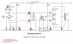
How about shewing us some test results & how you got them?That all depends on voltages. If you use a 300V B+ you'll have crap bass. If you use 150V B+ it'll be fine. Also I have a driver that swings enough to drive it a cathode follower - and berfore you say "but where do I get 600V?" a quadrupler off 120V or a doubler from 230V... A tripler from 120V gets you close enough, too... Also the 47uF/600V cap is B43541B8476M000 from TDK but you could use a series pair... I redesigned my boards to use a pair to avoid a single source part.
They're in a thread here somewhere... As I remember, for a certain amp, the test for 20Hz power was 2.3W with one, and 14.7W (same as 1kHz power) with both (6P1P push pull). I also remember 14W @ 30Hz with a pair of 6P45S in parallel and one VPT18 - the 250VA version. Add a second as shown and 113W@30Hz, It's also just a matter of the properties of the transformer. You can't swing 600V into a transformer designed for 230V and not expect issues 🙂 Put it another way. Run a 60Hz transformer on 25Hz power and find out how hot it gets... I'm no expert but I know the about the idea of core saturation etc and have seen 25Hz transformers rated for much lower power than they look lok they should be rated for.
I just see it how it works. Others here can write an essay about it though 🙂
I just see it how it works. Others here can write an essay about it though 🙂
Last edited:
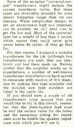
Yes, indeed! I still have to investigate further, but it appears that comparatively cheap 100 V line transfromers might be appropriate candidates for a Crowhurst arrangement. We need to observe the following, though:You can also use two "OT" xfmrs in the Norman Crowhurst "Twin Coupled" arrangement, to get doubled primary voltage, inductance and power.
- The candidate needs a multi-tapped primary.
- The primary impedance of each xformer calculates to 100²/lowest nominal wattage.
- There needs to be a tap called four times the lowest wattage tap. It becomes the center tap.
- The lowest wattage and the common terminal will become the plate or cathode, respectively, connections. Both taps need to be swapped for the cathode xformer.
- As the secondaries will be paralleled, the nominal output impedances need to be halved in comparison with what is printed onto the xformers. If I recall it correctly, Crowhurst didn't mention this in his original publication.
Best regards!
Hi Kay,Yes, indeed! I still have to investigate further, but it appears that comparatively cheap 100 V line transfromers might be appropriate candidates for a Crowhurst arrangement. We need to observe the following, though:
- The candidate needs a multi-tapped primary.
- The primary impedance of each xformer calculates to 100²/lowest nominal wattage.
- There needs to be a tap called four times the lowest wattage tap. It becomes the center tap.
- The lowest wattage and the common terminal will become the plate or cathode, respectively, connections. Both taps need to be swapped for the cathode xformer.
- As the secondaries will be paralleled, the nominal output impedances need to be halved in comparison with what is printed onto the xformers. If I recall it correctly, Crowhurst didn't mention this in his original publication.
Best regards!
There is a good link here that does all the hard work ...
ozvalveamps - 100v line output as OPT
There is an interesting correlation with power output and how useful the transformer is, because of the turns ratio. Sweet spot appears to be 20-25W.
Last edited:
This circuit is an example of the kind of thing that can be effectively avoided by using bootstrapping.That all depends on voltages. If you use a 300V B+ you'll have crap bass. If you use 150V B+ it'll be fine. Also I have a driver that swings enough to drive it a cathode follower - and berfore you say "but where do I get 600V?" a quadrupler off 120V or a doubler from 230V... A tripler from 120V gets you close enough, too... Also the 47uF/600V cap is B43541B8476M000 from TDK but you could use a series pair... I redesigned my boards to use a pair to avoid a single source part.
So the taps on a UL transformer can accomplish that. Or even simpler, a simple mod of two extra resistors on the driver will do.
The halved impedances shew up on his schematic. I pulled up the article, Crowhurst comments on it there too.Yes, indeed! I still have to investigate further, but it appears that comparatively cheap 100 V line transfromers might be appropriate candidates for a Crowhurst arrangement. We need to observe the following, though:
- The candidate needs a multi-tapped primary.
- The primary impedance of each xformer calculates to 100²/lowest nominal wattage.
- There needs to be a tap called four times the lowest wattage tap. It becomes the center tap.
- The lowest wattage and the common terminal will become the plate or cathode, respectively, connections. Both taps need to be swapped for the cathode xformer.
- As the secondaries will be paralleled, the nominal output impedances need to be halved in comparison with what is printed onto the xformers. If I recall it correctly, Crowhurst didn't mention this in his original publication.
Best regards!
Attachments
No, it doesn't, as the speaker terminals still are named 4 Ω, 8 Ω and 16 Ω. I can't imagine the OT's were 8, 16 and 32 Ω. Were they? Anyway, I don't have his article handy at the moment, so I had to rely on my memory.The halved impedances shew up on his schematic. I pulled up the article, Crowhurst comments on it there too.
Best regards!
Sorry, now I've found in the BOM that the specified transformers indeed are 8, 16 and 32 Ω 😏. Quite unusual, I'd say.
Best regards!
Best regards!
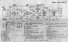
For those interested in Crowhurst's Twin Coupled Amp, here are links to the magazines they were published in.
And the link to magazines of the electronics industry during its history, a very good resource.
Radio Museum link to magazines
http://www.americanradiohistory.com/index.htm
https://worldradiohistory.com/Archive-Radio-Electronics/50s/1957/Radio-Electronics-1957-11.pdf
https://worldradiohistory.com/Archive-Radio-Electronics/60s/1960/Radio-Electronics-1960-06.pdf
https://worldradiohistory.com/Archive-Radio-Electronics/60s/1960/Radio-Electronics-1960-10.pdf
And Crowhurst's comments on his purpose built OPTs
Attachments
I have gravitated towards this circuit to base the amplifier on. I have a couple of signal transformers that ought to work for the input phase splitter.

http://www.tube-amps.net/EA_Hashimoto_EL34_PP_NNFB_02.htm
I have similar enough iron, and some 12BH7s etc. I have the intention of making "tube rolling friendly" for the small tube (adjustable current source for the input differential pair?), and probably fixed bias for the output tubes.
http://www.tube-amps.net/EA_Hashimoto_EL34_PP_NNFB_02.htm
I have similar enough iron, and some 12BH7s etc. I have the intention of making "tube rolling friendly" for the small tube (adjustable current source for the input differential pair?), and probably fixed bias for the output tubes.
hbc,
You want Tube Rolling Friendly?
Push Pull amplifiers:
1. If you use fixed bias for the output tubes, you need to:
Either . . . use separate Adjustable fixed bias for each output tube,
Or . . . use very well matched output tubes.
2. If you use self bias for the output tubes, you need to:
Either . . . use separate individual bias resistors and bypass caps, for each output tube,
Or . . . use very well matched output tubes.
Note: Your schematic is obscured by some other image on top.
Performance might be improved by omitting the 0.47 microF cathode bypass cap on the ECC80.I have gravitated towards this circuit to base the amplifier on. I have a couple of signal transformers that ought to work for the input phase splitter.
View attachment 1019535
http://www.tube-amps.net/EA_Hashimoto_EL34_PP_NNFB_02.htm
I have similar enough iron, and some 12BH7s etc. I have the intention of making "tube rolling friendly" for the small tube (adjustable current source for the input differential pair?), and probably fixed bias for the output tubes.
Something to measure on the finished amp.
12ax7 and 6922 boosted with NPN driver delivers 30w from a 150v b+ using a 10w 70v transformer.
The TX is only 10 w at 35hz, over 75hz its 30w
Highs go to 60khz.
The TX is only 10 w at 35hz, over 75hz its 30w
Highs go to 60khz.
hmm CV4060, interesting tube. descendant of the 12e1. but looks nice and not that expensive in the UK,
I have a tendency to make things complicated and I am internally debating with myself, should I use fixed bias or not. I like it and it sounds good to me, but the simplicity of cathode bias is attractive, and Push Pull amplifiers like well balanced current through the output transformers. Do we have any favorable or not opinion of using current sources connected to the power tube cathode, with a bypass capacitor.
I have a tendency to make things complicated and I am internally debating with myself, should I use fixed bias or not. I like it and it sounds good to me, but the simplicity of cathode bias is attractive, and Push Pull amplifiers like well balanced current through the output transformers. Do we have any favorable or not opinion of using current sources connected to the power tube cathode, with a bypass capacitor.
If you are an experienced builder it should be OK to go fixed bias. The triode mu of ~5 indicates there could be DC stabilityhmm CV4060, interesting tube. descendant of the 12e1. but looks nice and not that expensive in the UK,
I have a tendency to make things complicated and I am internally debating with myself, should I use fixed bias or not. I like it and it sounds good to me, but the simplicity of cathode bias is attractive, and Push Pull amplifiers like well balanced current through the output transformers. Do we have any favorable or not opinion of using current sources connected to the power tube cathode, with a bypass capacitor.
problems with fixed bias, the safe alternative is cathode bias.
Check out keggers 6AV5 PP triode amp over at Audiokarma.
https://audiokarma.org/forums/index.php?threads/diy-6av5-amplifier-want-to-build-one-or-two.309374/
https://audiokarma.org/forums/index.php?threads/diy-6av5-amplifier-want-to-build-one-or-two.309374/
Attachments
Last edited:
- Home
- Amplifiers
- Tubes / Valves
- Help deciding on a low cost 15-20 watt triode push-pull amplifier design