Where?
Indeed, i am rather mystified about the practical benefits of this arrangement
I see the Gunderson cct in it's patent is very different (on what it capable of) than the one that is used in Rotel amp.
The one in the patent is capable of EC, because it has fixed/stiff level shifter by D20.
In the Rotel amp, this feature disappears because it uses voltage divider to feed base of Q24.
In practical amp manufacturing, Rotel approach can be understood, it saves many additional cost. But the one in the patent (with D20) is the real capability of this approach. It needs higher (other) supply rail for front end, though.
Using the patent's cct (with D20) in practical amp with the same rail for front end and final stage not only spoil the max output voltage capability (rail efficiency), but in THD meter can result in worse THD, because of severe clipping of front end when output voltage approaching rail voltage.
I don't know what's the Gunderson's patent do in Rotel amp. They are 2 different thing, although the difference is only using zener and voltage divider for feeding base of Q24.
Mainly to split heat dissipation of VAS transistor?
The zener does not make it error correcting. It does the same as the potential divider. Yes it may lower headroom, but not by much as it only needs to be about 4V (yes that's quite a few watts, but a bootstrap or higher pre-driver rails undo that.)
The modest improvement found on a real design is interesting. However, if this turned out to be a miracle cure to remove all of the driver voltage distortion completely, there are plenty of other distortion mechanisms to give distortion at high frequencies, which would dominate after this mechanism is isolated. Those other distortions will not be improved as IT IS NOT ERROR CORRECTION. Honest.
The modest improvement found on a real design is interesting. However, if this turned out to be a miracle cure to remove all of the driver voltage distortion completely, there are plenty of other distortion mechanisms to give distortion at high frequencies, which would dominate after this mechanism is isolated. Those other distortions will not be improved as IT IS NOT ERROR CORRECTION. Honest.

lumanauw said:I don't know what's the Gunderson's patent do in Rotel amp. They are 2 different thing...
Exactly the same principal...
lumanauw said:The one in the patent is capable of EC....
Nyet.

jagwap said:.........if this turned out to be a miracle cure to remove all of the driver voltage distortion completely....
Actually, it, apparently, is meant to be a 'miracle cure' for output stage distortion...

Honest.
OK. Don't be angry with me 😀 OK, it is not EC, but it has feedback loop. Every feedback loop has capability to reduce distortion, just how far? It depends on reserve energy that is there to fix things. This Gunderson has very little of that energy, cause all the current is provided by Q23, not coming or not going elsewhere. Little, but it doesn't mean it don't do somekind of EC. Even EC done by the input differential pair +VAS has it's limit when headed with classB (not AB) or class C output stage.Nyet.
Higher predriver rails, yes it will do. But bootstrap, no, it won't help. If bootstrap is placed on Q24's base it makes worse case than plain voltage divider. Putting bootstrap on Q24's emitor, not it will not be an audio power amp. Bootstrap (capable of higher voltage than rail voltage) should be placed on upper of R24, then bootstrap can do something in this Gunderson cct.yes that's quite a few watts, but a bootstrap or higher pre-driver rails undo that.)
So,...what is the meaning of upper left and upper right graph of attachment in post #66?
Got VAS!
Here’s a toy amp comparison, top plot compares distortion with/without the “Gunderson stage”
The plot does show some minor potential for distortion reduction – about 50 dB for odd harmonics in this sim
While I would love to rub in a certain similarity to Gunderson’s patent and point out that distortion improvement is most noticeable at high frequencies where, as I earlier mentioned the low AC impedance of the VAS gives a larger local loop gain to the Q24,25 composite I must confess that the practical usefulness is questionable
When the output stage has reasonably low Vbe voltage distortion as we would all strive for with Class AB bias the distortion reduction of the Gunderson connection disappears
So the Gunderson circuit seems to be most suited to “saving” a amp with a really crappy underbiased Class B output from excessive crossover distortion
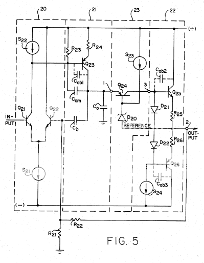
for those wishing to judge whether there is any relation between my sim circuit and the patent:
Here’s a toy amp comparison, top plot compares distortion with/without the “Gunderson stage”
The plot does show some minor potential for distortion reduction – about 50 dB for odd harmonics in this sim
While I would love to rub in a certain similarity to Gunderson’s patent and point out that distortion improvement is most noticeable at high frequencies where, as I earlier mentioned the low AC impedance of the VAS gives a larger local loop gain to the Q24,25 composite I must confess that the practical usefulness is questionable
When the output stage has reasonably low Vbe voltage distortion as we would all strive for with Class AB bias the distortion reduction of the Gunderson connection disappears
So the Gunderson circuit seems to be most suited to “saving” a amp with a really crappy underbiased Class B output from excessive crossover distortion
for those wishing to judge whether there is any relation between my sim circuit and the patent:
Attachments
Got Bias!
Added some bias diodes so there is now little left but a few ideal sources in my sim circuit’s approximation of the patent
Bumped the signal back up to 11 V output amplitude to exercise the output transistors’ current gain
Plotted the current gain of the output transistors (where the |Ic| > 1mA to avoid divide by zero spikes)
I think the beta variations can explain the 2nd and 3rd harmonics in the fft pretty well
2nd harmonic comes from unequal average Beta between the upper and lower output Qs (yellow and blue traces, right vert legend)
3rd harmonic comes from the compression from the ~ 20% droop of beta near the peaks (Ic ~= 110 mA) visible in both upper and lower output transistor beta curves
at 5KHz and above we can see Gunderson correction of crossover error harmonics from the still slightly under biased Class B operation – but the crossover distortion harmonic tail level is much less than my previous sim with 0 bias
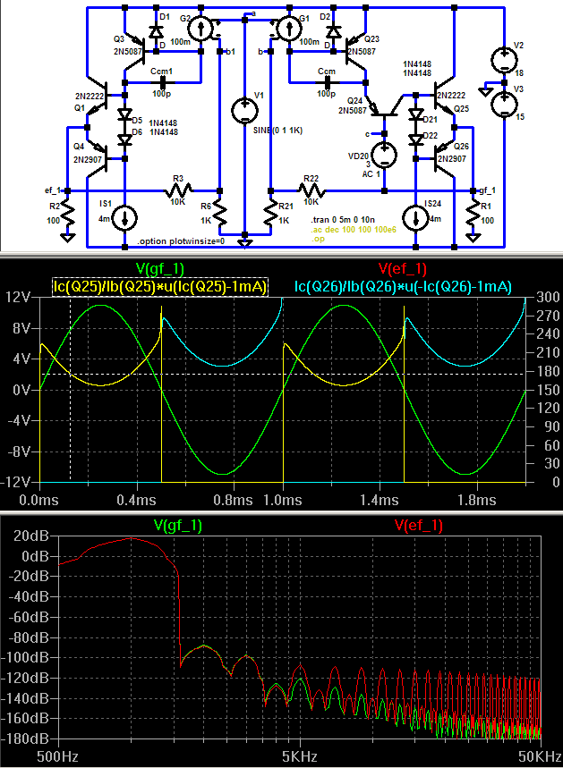
also note the ~ 20 dB/decade increasing distortion reduction of the Gunderson as frequency rises from 5 – 50 KHz, I think this slope is explainable by increasing local Q24,5,6 loop gain as the Ccm compensated VAS output impedance drops with increasing frequency
I think this sim simultaneously illustrates the Gunderson operation and points out its impracticality - the 1st few harmonics are likely dominated by output device current gain errors which the Gunderson circuit cannot correct – and where the sim shows some correction/distortion reduction the errors are already below any recorded music’s S/N at –120 to –140 dB
Added some bias diodes so there is now little left but a few ideal sources in my sim circuit’s approximation of the patent
Bumped the signal back up to 11 V output amplitude to exercise the output transistors’ current gain
Plotted the current gain of the output transistors (where the |Ic| > 1mA to avoid divide by zero spikes)
I think the beta variations can explain the 2nd and 3rd harmonics in the fft pretty well
2nd harmonic comes from unequal average Beta between the upper and lower output Qs (yellow and blue traces, right vert legend)
3rd harmonic comes from the compression from the ~ 20% droop of beta near the peaks (Ic ~= 110 mA) visible in both upper and lower output transistor beta curves
at 5KHz and above we can see Gunderson correction of crossover error harmonics from the still slightly under biased Class B operation – but the crossover distortion harmonic tail level is much less than my previous sim with 0 bias
also note the ~ 20 dB/decade increasing distortion reduction of the Gunderson as frequency rises from 5 – 50 KHz, I think this slope is explainable by increasing local Q24,5,6 loop gain as the Ccm compensated VAS output impedance drops with increasing frequency
I think this sim simultaneously illustrates the Gunderson operation and points out its impracticality - the 1st few harmonics are likely dominated by output device current gain errors which the Gunderson circuit cannot correct – and where the sim shows some correction/distortion reduction the errors are already below any recorded music’s S/N at –120 to –140 dB
Attachments
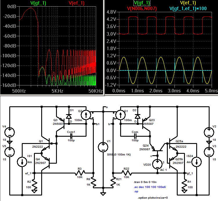
Any argument about distortion reduction and feedback needs some AC loop gain plots
Top circuit is a slightly modified circuit attempting to measure the local loop gain of the Gunderson compound transistor in the toy amp with VAS/Ccm driving impedance
It is desirable to cover a range of operating points – in under biased Class B the output Qs Ic and gain varies over a huge range – so I introduced Vos in the V1 sine source to set differing DC bias points for a series of stepped AC analysis
To disable the global loop in the plot I shorted node “b” to gnd with a 10 F Cap (spice trick) and moved the AC 1 excitation to VD20 – inside the Gunderson compound feedback loop
The simple Middlebrook test in the center AC plot shows rising local loop gain inside the Q24/25,6 compound transistor starting from ~ 500 Hz frequency where the VAS impedance becomes lower than the impedance seen at Q25,26 base (upper/left-most hump is phase, LtSpice still has plotting bug that doesn’t dash all of the phase traces in a plot of a equation - the loop gain curves rise from ~ 0 dB @ 100-500 Hz to peak ~ 55 dB @ 300 – 600 KHz)
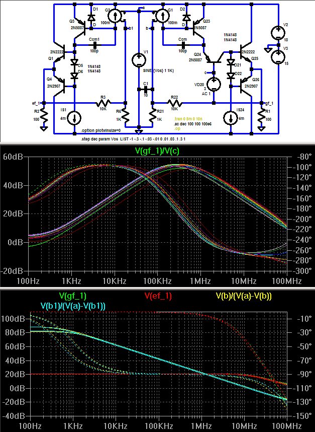
The bottom plot has the AC source moved to V1 input and the loop shorting C is removed – the loop gain of both circuits are plotted for the various bias steps, the purpose of this plot of global loop gain is to see if big loop gain differences exist that might explain the distortion differences – doesn’t look like it (only the 0 and 1 V Vos steps are plotted here)
as usual .asc attachements are LtSpice circuit files - just rename without the .txt extension
Top circuit is a slightly modified circuit attempting to measure the local loop gain of the Gunderson compound transistor in the toy amp with VAS/Ccm driving impedance
It is desirable to cover a range of operating points – in under biased Class B the output Qs Ic and gain varies over a huge range – so I introduced Vos in the V1 sine source to set differing DC bias points for a series of stepped AC analysis
To disable the global loop in the plot I shorted node “b” to gnd with a 10 F Cap (spice trick) and moved the AC 1 excitation to VD20 – inside the Gunderson compound feedback loop
The simple Middlebrook test in the center AC plot shows rising local loop gain inside the Q24/25,6 compound transistor starting from ~ 500 Hz frequency where the VAS impedance becomes lower than the impedance seen at Q25,26 base (upper/left-most hump is phase, LtSpice still has plotting bug that doesn’t dash all of the phase traces in a plot of a equation - the loop gain curves rise from ~ 0 dB @ 100-500 Hz to peak ~ 55 dB @ 300 – 600 KHz)
The bottom plot has the AC source moved to V1 input and the loop shorting C is removed – the loop gain of both circuits are plotted for the various bias steps, the purpose of this plot of global loop gain is to see if big loop gain differences exist that might explain the distortion differences – doesn’t look like it (only the 0 and 1 V Vos steps are plotted here)
as usual .asc attachements are LtSpice circuit files - just rename without the .txt extension
Attachments
Nice, JCX 😀
You got any sim of Gunderson topology that uses voltage divider instead of zener for base of Q24?
You got any sim of Gunderson topology that uses voltage divider instead of zener for base of Q24?
jcx said:Any argument about distortion reduction and feedback needs some AC loop gain plots
[snip] the loop gain of both circuits are plotted for the various bias steps, the purpose of this plot of global loop gain is to see if big loop gain differences exist that might explain the distortion differences – doesn’t look like it (only the 0 and 1 V Vos steps are plotted here)
as usual .asc attachements are LtSpice circuit files - just rename without the .txt extension
Hi Jcx,
A basic question - is distortion reduction possible at all if there is no additional loop gain? I think it is - look at Hawksford error correction, where additional loop gain is almost non-existing (less than a dB) but distortion reduction is often dramatic.
I'm not saying the Guderson circuit is Hawksford EC - it isn't - but there may be another effect not showing up in the loop gain plots. What do you say?
Jan Didden
Great work JCX. Cheers.😎
However, your loop-gain plots are in error.
You cannot plot minor loop transmission without decoupling said loop from the global loop at frequencies of interest.
Additionally, i suspect your simplified loop-gain analysis is severely compromised by loading at the point of insertion.
Indeed, i suspect the rather disappointing performance of Gunderson is due to the fact that the scheme acts in phase opposition to the foward-path voltage delivered by the second stage.
This, therefore, is degenerative feedback, and reduces both minor and major loop gain quite drastically, which defeats its reson d'etre.
I don't know if it is right, but my thinking that error correction can be done in 2 way. Add and substract (of current or voltage).
A system that don't have other energy source (additional CCS or voltage source or reserve) still can be doing EC by "substracting" current or voltage until the desireable equilibrum is achieved.
A system that can only "add" or "substract" will be not perfect EC system, a perfect one should be able to do both "add" and "substract". It seems this Gunderson is only can do "substract", that the max correction is still limited by current from Q23. Q24 does some EC by being a "stop valve"
Incidentally...
...bias for the 'cascode' device need not be provided by a voltage divider after all....(if a 'non-complementary' TIS is used).
Just connect 'cascode' BJT directly to output rail with a small base ballast resistor...
...bias for the 'cascode' device need not be provided by a voltage divider after all....(if a 'non-complementary' TIS is used).
Just connect 'cascode' BJT directly to output rail with a small base ballast resistor...
jcx said:Any argument about distortion reduction and feedback needs some AC loop gain plots
...To disable the global loop in the plot I shorted node “b” to gnd with a 10 F Cap (spice trick) and moved the AC 1 excitation to VD20 – inside the Gunderson compound feedback loop
The simple Middlebrook test ...
Global loop was disabled for the inner/Gunderson loop gain plot, 10 F kinda pretty sorta effectively shorts out global feedback while still allowing LtSpice to find DC operating point ( R21\\R22 * C1 ~ 1000 seconds => ~ 120 dB feedback attn @ > 100 Hz)
I believe the conditions for the simple test are reasonably met - large impedance diff seen at either end of test AC V source - at least to low MHz (100 Ohm R1 load || Q25,6 emitters vs Q24 base)
of course the loop gain probe subcircuit approach can be more accurate but it is awkward with multiple instances in comparing the 2 circuits and next to impossible to use with stepped bias
I would welcome anyone playing with my sims to improve the accuracy or illustrate where I’ve gone astray – but that requires reading my explanations and studying the circuits I simed
- Home
- Amplifiers
- Solid State
- Gunderson compensation..