postscript...
what on earth is wrong with yahoo mail...i can't get in for love or money...
Anyone have a similar problem?
what on earth is wrong with yahoo mail...i can't get in for love or money...
Anyone have a similar problem?
Regarding the variant with resistive divider, there is a difference between Rotel and Slone. Rotel connects Cm at the collector of the VAS transistor, while Slone connects it at the collector of the cascode transistor, thus not isolating it from the OPS (as far as I can see). This makes it even more questionable to label as a Gunderson circuit.
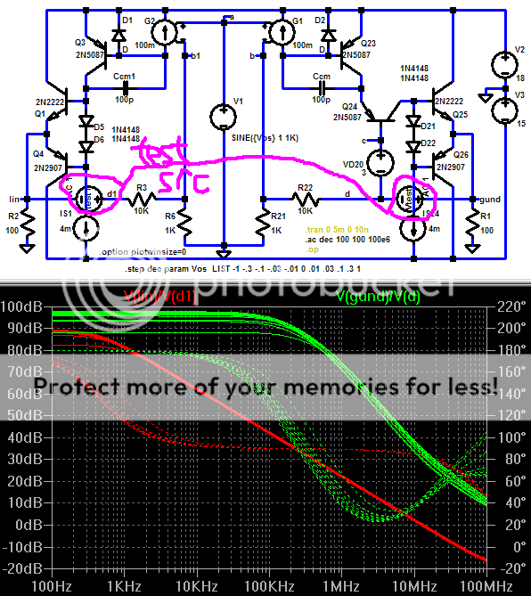
Having thought a little bit more about it and digging up my old Spice model of the Optimos and running a few quick, not very comprehensive simulations, I am now leaning towards a guess that in Slones case this is indeed intended as a soft clipping device to be able to go closer to the rails and thus squeeze out a little bit more power. I question the benefit, though, since we gain very little extra margin over ordinary fixed cascodes, if using a small bias voltage for these. OTOH, a higher bias voltage is preferrable to linearise the VAS transistor, but then the input and VAS should preferrably be run at a higher rail voltage than the OPS, which Slone most likely wanted to avoid. Simulations even seem to indicate that as long as ordinary cascodes are not clipping, they give a somewhat lower distorsion. That should be taken with a pinch of salt though, since close to clipping the VAS transistor works close to saturation, where Spice models, especially the ones I use in this case, are notoriously bad.
BTW, this is a slightly abstracted verision of the Optimos (some ideal current and voltage sources used, and a few resistors not in the original design and only used for simulation experiments).
The plot thickens...
You are absolutely right, Christer, in respect of Slone being different from Gunderson.
You are absolutely right, Christer, in respect of Slone being different from Gunderson.
Re: Hi jcx..
To the Gunderson Loop maybe? 🙂
http://www.trails.com/topo.asp?trailid=BGW020-050
mikeks said:
Journey to where?
To the Gunderson Loop maybe? 🙂
http://www.trails.com/topo.asp?trailid=BGW020-050
Christer, are you, by any chance, having any trouble logging into Yahoo mail?
All i get is 'Error 502F'
All i get is 'Error 502F'
mikeks said:Christer, are you, by any chance, having any trouble logging into Yahoo mail?
All i get is 'Error 502F'
I don't use it. I could access the main page for loggin in though, if that is of any help.
I have an extra email at msn that I used in cases where I didn't want to expose my usual address for risk of spam etc. but have quit using it since it started to get impossible to log in a couple of years ago.
If it hasn't been for several days, it is probably some temporary problem.

My Post #108: http://www.diyaudio.com/forums/showthread.php?postid=967159#post967159
Shows the Gunderson as a local feedback loop enclosing the output stage
My sim in Post # 90:
http://www.diyaudio.com/forums/showthread.php?postid=966869#post966869
shows gain in this loop – kinda the definition of it actually being usefully viewed as a feedback loop – don’t you think? – that would be the middle plot in that img
In some of the intervening posts mikes makes some objections based on some mutual communication difficulties, after clearing them up mikes finds even more gain in his sim of the loop I am calling the “Gunderson” loop– due to differing idealizations
Mike’s Post# 111,2:
http://www.diyaudio.com/forums/showthread.php?postid=967194#post967194
2 investigators using differing tools and circuit approximations find gain in the “Gunderson Loop” - yet we have a mix of insight and blindness in this post:
It is really strange in light of the above to insist that there is no error correcting negative feedback loop in Gunderson’s circuit – did jagwap read and understand any of my posts?
But jagwap hits the nail on the head with the point that Mike seems to be avoiding – there is correction of output stage Vbe error due to the large gain available at high frequencies inside the “Gunderson local feedback loop” enclosing the output transistors AND the distortion reduction disappears when you apply the Gunderson circuit to a already low distortion output stage – certainly to one where Ib/Beta errors dominate
My toy amp sim without bias in the complementary output stage shows 50 dB ! reduction of crossover switching errors that can only be attributed to the loop gain inside the Q24/25,6 loop in my Post #88:
http://www.diyaudio.com/forums/showthread.php?postid=966758#post966758
my next sim in the following post #89 shows that the distortion reduction attributable to the Gunderson Loop holds up in principle in a lightly biased Class AB stage (Ic(Q25,6)~= 0.8 mA) – although admittedly the difference is only appreciable in sim, the levels where these circuit’s harmonics differ are below any real predictive power of the models and likely buried in the noise of real circuit and signals – again “proof” that Gunderson’s circuit doesn’t help where it matters when the output stage is pretty linear already
Mike,
I think the “problem” with your approach is that the Gunderson connection in fact doesn’t change the impedance seen by the VAS output – with 99%+ current transfer from Q24 emitter to the Q25,6 base – and in the small signal linear approximation the “bootstrap” of Q24’s emitter by the Q25,6 follower driving its base keeps the Q24 emitter close to Q25,6 base potential – the base impedance of the Q25,6 output stage is pretty nearly transferred thru to Q24 emitter – with a “good” output stage of nearly linear unity gain
Since the Gunderson connection doesn’t change the impedance seen at the VAS the "Global" loop gain we both looked at earlier wasn’t changed as both of our previous sims have established so we have to look elsewhere than in the "global" loop gain plots we both used
I propose looking at the return difference around the output Q25,6 as shown below, I would like to believe the difference in these 2 loop gain plots is the gain I plotted earlier as the “Gunderson Loop” local feedback gain:
now we have more gain visible around the output stage even though much of it is tied up inside the local unity gain “Gunderson Loop” of Q24/25,6 so that it was not visible in our loop gain plots that didn’t cut the inner Gunderson loop – this extra gain should be evident in output impedance plots – anyone else want to try that sim?
Shows the Gunderson as a local feedback loop enclosing the output stage
My sim in Post # 90:
http://www.diyaudio.com/forums/showthread.php?postid=966869#post966869
shows gain in this loop – kinda the definition of it actually being usefully viewed as a feedback loop – don’t you think? – that would be the middle plot in that img
In some of the intervening posts mikes makes some objections based on some mutual communication difficulties, after clearing them up mikes finds even more gain in his sim of the loop I am calling the “Gunderson” loop– due to differing idealizations
Mike’s Post# 111,2:
http://www.diyaudio.com/forums/showthread.php?postid=967194#post967194
2 investigators using differing tools and circuit approximations find gain in the “Gunderson Loop” - yet we have a mix of insight and blindness in this post:
jagwap said:
...In your last scem there is no output stange, so there will virtually no non linearities at the VAS, so no difference in performance.
At least it's been proved it isn't an error correcting system now.
It is really strange in light of the above to insist that there is no error correcting negative feedback loop in Gunderson’s circuit – did jagwap read and understand any of my posts?
But jagwap hits the nail on the head with the point that Mike seems to be avoiding – there is correction of output stage Vbe error due to the large gain available at high frequencies inside the “Gunderson local feedback loop” enclosing the output transistors AND the distortion reduction disappears when you apply the Gunderson circuit to a already low distortion output stage – certainly to one where Ib/Beta errors dominate
My toy amp sim without bias in the complementary output stage shows 50 dB ! reduction of crossover switching errors that can only be attributed to the loop gain inside the Q24/25,6 loop in my Post #88:
http://www.diyaudio.com/forums/showthread.php?postid=966758#post966758
my next sim in the following post #89 shows that the distortion reduction attributable to the Gunderson Loop holds up in principle in a lightly biased Class AB stage (Ic(Q25,6)~= 0.8 mA) – although admittedly the difference is only appreciable in sim, the levels where these circuit’s harmonics differ are below any real predictive power of the models and likely buried in the noise of real circuit and signals – again “proof” that Gunderson’s circuit doesn’t help where it matters when the output stage is pretty linear already
Mike,
I think the “problem” with your approach is that the Gunderson connection in fact doesn’t change the impedance seen by the VAS output – with 99%+ current transfer from Q24 emitter to the Q25,6 base – and in the small signal linear approximation the “bootstrap” of Q24’s emitter by the Q25,6 follower driving its base keeps the Q24 emitter close to Q25,6 base potential – the base impedance of the Q25,6 output stage is pretty nearly transferred thru to Q24 emitter – with a “good” output stage of nearly linear unity gain
Since the Gunderson connection doesn’t change the impedance seen at the VAS the "Global" loop gain we both looked at earlier wasn’t changed as both of our previous sims have established so we have to look elsewhere than in the "global" loop gain plots we both used
I propose looking at the return difference around the output Q25,6 as shown below, I would like to believe the difference in these 2 loop gain plots is the gain I plotted earlier as the “Gunderson Loop” local feedback gain:
now we have more gain visible around the output stage even though much of it is tied up inside the local unity gain “Gunderson Loop” of Q24/25,6 so that it was not visible in our loop gain plots that didn’t cut the inner Gunderson loop – this extra gain should be evident in output impedance plots – anyone else want to try that sim?
jcx said:But jagwap hits the nail on the head with the point that Mike seems to be avoiding – there is correction of output stage Vbe error due to the large gain available at high frequencies inside the “Gunderson local feedback loop” enclosing the output transistors AND the distortion reduction disappears when you apply the Gunderson circuit to a already low distortion output stage – certainly to one where Ib/Beta errors dominate...
Hi jcx 🙂
On the contrary, i did not, in fact, contest your averment that switching distortion in an unbiased output stage may be reduced by Gunderson.
My view is that this is of dubious utility as the reduction is not also manifest with a properly biased output stage, an observation you've also made.
After all, in practice, one seeks not to employ intentionally unbiased output stages, doesn't one?
jcx said:– again “proof” that Gunderson’s circuit doesn’t help where it matters when the output stage is pretty linear already..
My sentiments precisely..
jcx said:
Mike,
I think the “problem” with your approach is that the Gunderson connection in fact doesn’t change the impedance seen by the VAS output...
Perhaps i wasn't a paragon of clarity in an earlier post of mine in this respect.
In other words, Gunderson doesn't alter the net modulus of impedance at the point at which the minor (compensation) loop derives its feedback voltage.
It this node, and NOT the node to which the output stage is connected, that i referred to as the TIS output.
Apologies for any inardvertent confusion occasioned by my earlier post.
Jcx, Q24 does change the impedance seen by the VAS stage. This is because although the emitter current of Q24 is almost the same, at LF, as the output stage input current, the Vbe of Q24 is different from the Vb-Vout of the output stage. So the impedance seen by the VAS (Vb/Ivas) will be changed by Q24 (when Vb=Ve of Q24) if the Gm characteristic of Q24 is different from that of the output stage.I think the “problem” with your approach is that the Gunderson connection in fact doesn’t change the impedance seen by the VAS output – with 99%+ current transfer from Q24 emitter to the Q25,6 base – and in the small signal linear approximation the “bootstrap” of Q24’s emitter by the Q25,6 follower driving its base keeps the Q24 emitter close to Q25,6 base potential – the base impedance of the Q25,6 output stage is pretty nearly transferred thru to Q24 emitter – with a “good” output stage of nearly linear unity gain
traderbam said:
Jcx, Q24 does change the impedance seen by the VAS stage. This is because although the emitter current of Q24 is almost the same, at LF, as the output stage input current, the Vbe of Q24 is different from the Vb-Vout of the output stage. So the impedance seen by the VAS (Vb/Ivas) will be changed by Q24 (when Vb=Ve of Q24) if the Gm characteristic of Q24 is different from that of the output stage.
That's what I thought, the Vas (or TIS) is working into a low-impedance node with Q24, without Q24 it would work into a high-impedance node (the output stage input). I think this is crucial for the Gunderson concept.
Jan Didden
You think a Class B output stage is linear? Interesting.
If you look at the voltage on the base of the driver when a 4 ohm load is applied, you'll see some nasty dicontinuities.
I've done a quick simulation of an amp with and without Q24, and at 20K the THD falls by a factor of 4. It may fall by more if the residual THD was less.
It's all laid out in the patent.
janneman said:
That's what I thought, the Vas (or TIS) is working into a low-impedance node with Q24, without Q24 it would work into a high-impedance node (the output stage input). I think this is crucial for the Gunderson concept.
Jan Didden
But in the case of a cascoded VAS (TIS) it works into a low imdedance node. It's the current going into the emitter of the cascode which is passed straight through inot the high impedance node of the drivers on the collector. The same thing happens with the Gunderson concept. The output current of the VAS is transferred to the collector of Q24 in practical terms unaffected. It operates much like a cascode, except it is tied to the output instead of a reference relative to the VAS. As such it doesn't have the early effect and hf benefits of a cascode, but isolates the driver voltage. In my simulation I tried it with a VAS cascode as well to try to get the other distortions to a minimum and it works fine.
There is some stability problems with a triple emitter follower, but with just driver and output it shows some condsiderable benefit. However, what's stable on a simulation, real life can be "interesting"...
In the non-G case, VAS output voltage is Vout + (Vb-Vout) of the output stage.
In the G case, VAS output voltage is Vout + Vbe of Q24.
For the same Vout, the current supplied by the output stage will be identical...and the VAS output current will be almost the same in either case (neglecting parasitic impedances of Q24 and assuming Q24 beta is very high).
In the G case, VAS output voltage is Vout + Vbe of Q24.
For the same Vout, the current supplied by the output stage will be identical...and the VAS output current will be almost the same in either case (neglecting parasitic impedances of Q24 and assuming Q24 beta is very high).
traderbam said:In the non-G case, VAS output voltage is Vout + (Vb-Vout) of the output stage.
In the G case, VAS output voltage is Vout + Vbe of Q24.
For the same Vout, the current supplied by the output stage will be identical...and the VAS output current will be almost the same in either case (neglecting parasitic impedances of Q24 and assuming Q24 beta is very high).
So, assuming that Vbe is relatively constant (much more so than (Vb-Vout), it indeed appears that the Vas output voltage misses the b-e irregularities of the output stage, and this as I see it is the 'isolation' effect G talks about.
If I interpreted it correctly, mikeks has made the point that the absence of these regularities also means that the Vas/TIS cannot use the inherent stage fb from the miller/comp cap to correct for them. But is that bad? Is that fb correction through the miller cap/Cdom actually good? I would say NO! The Vas/TIS output voltage (non-G case) MUST be non-linear if it is linearly current driving a non-linear (Zin output stage) impedance. The effect of any feedback through the miller cap / Cdom would make the Vas/TIS output voltage more linear. Since it drives a non-linear impedance, by necessity the drive current to the output stage (non-G cas) will become more non-linear. That is actually a worsening of the situation.
So, in this scenario and can see an improvement in the G case as it allows the Vas voltage to be linearized while avoiding 'un-linearizing' its drive current. It AVOIDS stage fb through the miller /Cdom and therefore improves the result. Maybe that is the real meaning of the 'isolation'.
Jan Didden
janneman said:
So, assuming that Vbe is relatively constant (much more so than (Vb-Vout), it indeed appears that the Vas output voltage misses the b-e irregularities of the output stage, and this as I see it is the 'isolation' effect G talks about.
If I interpreted it correctly, mikeks has made the point that the absence of these regularities also means that the Vas/TIS cannot use the inherent stage fb from the miller/comp cap to correct for them. But is that bad? Is that fb correction through the miller cap/Cdom actually good? I would say NO! The Vas/TIS output voltage (non-G case) MUST be non-linear if it is linearly current driving a non-linear (Zin output stage) impedance. The effect of any feedback through the miller cap / Cdom would make the Vas/TIS output voltage more linear. Since it drives a non-linear impedance, by necessity the drive current to the output stage (non-G cas) will become more non-linear. That is actually a worsening of the situation.
The modest feeback the Ccm will, at higher frequencies only, help the drive of the output stage. It's a useful side effect of the Ccm technique of stability compensation. The non linear behaviour of the output stage under load is corrected by the global feedback and as such the signal current (and it's pre-distroted signal to make a clean output) passing through the VAS will not change radically with or without Q24.
janneman said:
So, in this scenario and can see an improvement in the G case as it allows the Vas voltage to be linearized while avoiding 'un-linearizing' its drive current. It AVOIDS stage fb through the miller /Cdom and therefore improves the result. Maybe that is the real meaning of the 'isolation'.
Jan Didden
Yes

janneman said:That's what I thought, the Vas (or TIS) is working into a low-impedance node with Q24, without Q24 it would work into a high-impedance node (the output stage input). I think this is crucial for the Gunderson concept.
Jan Didden
Hi Jan,
That is exactly what i thought-initially.
For it seemed reasonable to assume that Q24 acts in a manner akin to that of the common-base transistor in cascode.
That this wasn't so was confirmed by the observation that simulated major and minor loop transmissions of a model amplifier with an ordinary cascode TIS are virtually identical in magnitude to the arrangement in which Q24 was included as the third 'cascoded' BJT in the second stage.
This proved that that Q24 has no effect, for good or evil, on the impedance modulus existing at it's emitter before and after insertion.
This is contrary to the characteristics of a BJT operating in true common-base mode.
If the later were true, the net impedance at the node from which minor-loop feedback is derived would be so small that the pole-splitting mechanism, otherwise provided by minor-loop compensation, would be virtually disabled, and continuous oscillation would ensue.
- Home
- Amplifiers
- Solid State
- Gunderson compensation..