-15v power supply experiments
To builders of distinction, I can offer some observation on -15v PS that seems promising re sound quality.
I built my PS based on some personal experience and that of Oliver's Red Baron thread. But I did not do a bunch of testing of alternatives. After running for a few weeks, I was intrigued to see if tweaking this PS impacts sound, and it does.
Oliver uses super soft recovery diodes to feed 15 1800uf low esr caps with a film cap bypass to a salas shunt to the -15v input of the tda brd.
I built my -15v PS using its own hammond 229 transformer, same super soft diodes, but then crcrc using 1 cap - 20r - 6 caps - 16r - 6 caps with last bank bypassed with a BG F 50u. Sound after break in is very good. Big sound stage and good separation of instruments etc.
The first experiment was to see after if crcrc would yield different result than Olivers big bank of 12-15 caps. I simply shorted the resistor.
Result was immediately obvious degradation of sound. Not dramatic but clearly closed down some dynamics and closed up the sound stage. A bit more like listening to a machine than the performance.
This proved that the 3rd order filtering was better than a big bank of caps. Initially I attempted to build the supply using chokes that I had on hand. They proved to have too much resistance to provide enough current to fully power the shunt. The crowd over on the DDDAC thread is having great results using Lundahl filament chokes in their analogue supply. So without popping $200 for exotic chokes, I tried an experiment building a DIY filament choke and used it to replace the first resistor to build a clcrc PS.
Bingo! Surprisingly better, and clearly a keeper. It took the sound up an obvious notch in the direction of clean natural sound and all the adjectives we seek. i plan to buy a better choke to replace the second resistor to make a CLCLC filter.
A filter choke is a high current low H choke with very low R. In tube amps it is often a ferrite rod with 20 turns of magnet wire. I had on hand some ferrite toroid cores from surplus. About $2 ea and 2" in diameter. I also had a roll of 18gauge magent wire on hand so put those together and I had a ferrite choke. I wrapped one layer of wire around the torroid core. About 20 feet of wire. The resistance is 0.2R. I have no way of measuring the inductance but I suspect just a few mH at these currents.
I'll be using a Hammond choke in the second position. Something like 300mH and 6r. They are about $25. Those with deep pockets should try the Lundahl chokes used by the DDDAC team.
Last edited:
🙂 !
Did you compare Oliver board to the Distinction with the same parts & values and same powersupply conf ?
On the Net with some pictures of the Audial Model S you can see they use after the diodes bridge : rcrcr to feed the shunt regs !
Which diodes rectifier ref are populated please in your board ?
I believe also youhear a lot of difference because your Super E BG N conf on the -15V local decoupling near the pin 15 !
Did you try with one BG N cap only but with the shortest lead on the voltage rail, here Minus ?
🙂 !
Did you compare Oliver board to the Distinction with the same parts & values and same powersupply conf ?
No.. I have one his personal test board circa rev4. At some point I may plug it in. Right now don't want to disrupt current rig so much, so it remains a future opportunity for comparison.
On the Net with some pictures of the Audial Model S you can see they use after the diodes bridge : rcrcr to feed the shunt regs !
Which diodes rectifier ref are populated please in your board ?
Fairchild Stelth ISL9R460PF2 600V/4A/22ns
Mouser 512-ISL9R460PF2
Same as he uses and highly recommended.
I believe also youhear a lot of difference because your Super E BG N conf on the -15V local decoupling near the pin 15 !
Yes, well worth the add
Did you try with one BG N cap only but with the shortest lead on the voltage rail, here Minus ?
No, went straight to Super E as tight as possible to input. See earlier pic. I have had good results in the past simply soldering a BG N of modest size (4.7u) directly to tda pin -15v.
Heres a few more shots.
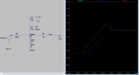
Output at my F5 playing 11025hz square wave -90db.
Looks a bit cleaner.
noise on F5 with 470r.JPG - with 470r
11025 F5 BCK.JPG - before, without a resistor
I see you managed to get rid of the mean spikes in the first picture... 😎
You talk about the rise-time still being quite high, so an increase of the resistor value to somewhere in the 1k to 1k5 range should be an option, I guess...
[QUOTE
I recently received a rather surprising valve o/p stage design from 'our man from Milan' and this is getting some attention now by Ryan - I have been a bit disappointed in nearly all of the valve o/p stages for this dac, for one reason or another, but this one seems to offer great potential with a minimum of exotic parts.
All the best.[/QUOTE]
Hello James
Which man from Milan do you talk about ?
I'm happy with a wave I/O and the Ian's I2StoPCM, so yes, there is defintly just not the sd card readers !
Shane (Ceglar member, country fellow of you and Ryan) who became a buddy, told me we really have to try the FIFO + reclocker if not already on our dacs... worth it with this chip. The TDA1541 has some good reservs ! 🙂
What tubes do you talk about in your new design please ? I will go myself with 6072a to beginn with, D3A or 6922 are not for the beginners in tubes layout as I am (never went to tubes but this year I will try !)
Distinction seems better than Red Baron if I read into the lines 😀
cheers
Perhaps, Ryan, a simple plug in board to fit some 'drilled out holes' on the existing board might be worth the initial trial for the input attenuator circuits - I think there some mention about feeding the returns to digital ground (rather than analogue gnd) and this may also require a separate +5V supply (or a simple RC or a CMx buffer)to the existing one .....
James!
Your right, another +5V will be necessary, RF noise going straight into my +2mA CCS can't do it much good. A CMx may very well be a good option, i have a few shunt pcbs + parts though... On the PCB i made - i put a basic LC config on there just to get by for testing purposes.
Speak later.
Ryan
hi Ryan, wouldn't it make sense for us to cut the tracks and insert a resistor to attenuate the signal? Maybe if you do another round of boards again at some stage, you could update it with the attenuator.
Hi Luke,
Yep, the thought crossed my mind. Much more testing first.
If you want to scrape the silk screen away and cut the trace, that would definitely suffice. If you didn't like the results you could put a 0R 1206 resistor/jumper there.
Yep, the thought crossed my mind. Much more testing first.
If you want to scrape the silk screen away and cut the trace, that would definitely suffice. If you didn't like the results you could put a 0R 1206 resistor/jumper there.
Listening session observations.
Some unfortunate results.
Sound stage/imaging has reduced in accuracy significantly with the 470r in series with the digital lines. Im getting a much more smeared sound stage. Made me feel like i had a blocked left ear - the image, mainly vocals was pulled to the right, which reminded me of how it used to sound before many of my upgrades. But strangely an apparent increase in detail? Maybe due to a change in dynamics, not sure. Cleaner power supplies?
Once i removed the attenuation circuit, imaging became more focused and centred with more realistic dynamics. Clearly better than before on all levels unfortunately.
All I could put this down to is an increase in on chip deterministic jitter - the triggering of the sample is more varied due to the slowed down rising edge of bck once latch enable in engaged.
Ah well, this is what testing is all about.
It might be better to keep the rising edge fast, but limit the amplitude and bias upto ~1.5V. (still reducing RF in order of magnitude from entering the chip) A possible solution may be to use a series of diodes in the signal path (as John Brown did in some of his tests).
Last edited:
Some words of advice from John Brown:
Hi dvb-project,
Resistive attenuators lead to less steep transients, this opens the door for trigger uncertainty in noisy environments.
That's why I suggested to directly connect FIFO BCK out to pin2. This is the best compromise given the practical drive circuit limitations.
I also suggest to use shortest possible connection between FIFO circuit and TDA1541A BCK input. With shortest possible I don't mean a few centimeters mut more like a few millimeters.
If you want to experiment with a BCK attenuator you could try a similar diode attenuator like with WS and DATA. The pull-up resistor value then has to be lowered to 120 Ohms. The resistor value needs to be as low as possible, but it's minimum value is limited by the typical 25mA max. output current of the FIFO reclocker.
Outstanding
Ryanj,
I know the disappointment after putting in 20 hrs of hard work only to find result is a step backwards.
You have however shown us great combination of engineering with common sense. Scope on one variable looked great.. but sound not good.
I hope you have the energy to take a second run at this with diode attenuator to see if the very sharp rise we have with modern signal source goes well with attenuated voltage.
Could turn out you have it perfect the first time. But now we will know that less is more.
Thanks again for publishing great work.
Walter
Hi Walter,
I'll take another stab at it eventually, just have to take a step back and have a good think about it, along with a fair bit of research.
None of this ever feels like work for me, and its satisfying knowing yourself and others can enjoy the ride.
Cheers.
I'll take another stab at it eventually, just have to take a step back and have a good think about it, along with a fair bit of research.
None of this ever feels like work for me, and its satisfying knowing yourself and others can enjoy the ride.
Cheers.
No need to rush it..
I cannot imagine better sound quality than I am getting now. So there is nothing that needs fixing.
I cannot imagine better sound quality than I am getting now. So there is nothing that needs fixing.
No need to rush it..
I cannot imagine better sound quality than I am getting now. So there is nothing that needs fixing.
Very true, the sound coming out of my speakers has changed so much over the past few years, at first i thought i needed to upgrade them. But as i've upgraded the DAC over the past years; it has proven just how good the TB W8-1772 full rangers really are. (Bob Brines TT-2000 cabinets)
I've been playing around with LTspice. Here is what i've found, its fairly self explanatory.
Blue trace is the signal coming out of i2s to pcm PCB.
Green trace is without the 22R - R3
Red trace is with R3
The Red trace looks a lot slower but is in fact ~700ps
I think this may be worth trying.
Ryan
Attachments
Looks great. This may be a dumb question.... would a small inductor on the V2 line help prevent noise from getting back into the +5v line? Or are you thinking a separate +5v source to feed attenuators on all the I2S lines?
Looks great. This may be a dumb question.... would a small inductor on the V2 line help prevent noise from getting back into the +5v line? Or are you thinking a separate +5v source to feed attenuators on all the I2S lines?
Ill plug it in to LTspice and see what happens. Although I remember John Brown saying it may cause ringing.
And yeah, Ill end up using another +5v supply anyway, but ill test with the +5v from TDA supply for now.
Hi Audiohifi,
It’s correct but use same split pull-up desistor with decoupling cap on BCK and DATA as well.
So you need 6 resistors and 3 decoupling caps in total.
Remove the 10mH choke, it causes ringing, emits EMI / picks up EMI. Two resistors with a decoupling cap will do fine.
Last edited:
BTW, I have had the same experience re speakers. I expected them to be the weak link in my system and first up to be replaced. I believe its the other way around. Source first, then linestage, amps and last speakers. It just keeps getting better as the source improves. Hard to justify the cost and disruption of a big speaker overhaul.
Yeah totally agree, its really surprising. Although i did the exact opposite... opps.
I had a look at the spice model and the cap (C2) is doing a great job at absorbing the ripple - Its measuring 533nVpp. Real world may be very different though.
I had a look at the spice model and the cap (C2) is doing a great job at absorbing the ripple - Its measuring 533nVpp. Real world may be very different though.
Hello,
I believe the same, the limitation in my system was always (so: is !) the numeric source and not the speakers which oddly is able to glue to the DAC quality : speakers can became harsh or soft, soundstage wild or not, bass dull or not, etc !
What is the rise time at the output of the whole chain of Ian's devices : fifo + reclocker+ I2StoPCM (+ Ian's isolator? better than the embeded one of the Wave I/O) !
Worth to ask to Ian to simulate your work or is the rise time is simply equal to the one "generated"by the last board (here the I2toPCM or the Ian's standalone isolator board ?
All the uf.l 6" to 4" length interconections have no major influence on the pico second rise time ?
Worth to make a local decoupling of the I2S signal (is it possible in electronic to decouple so low signal ?) just at the physical input of the TDA pins 1 to 4, or does it add more problem than it resolves ?
http://www.diyaudio.com/forums/digital-source/30025-decoupling-tda1541a-23.html#post2667110 : "the I2S attenuators will cause significant local currents, so layout needs some care in other ways."
http://www.diyaudio.com/forums/digital-source/30025-decoupling-tda1541a-15.html#post2657492
http://www.diyaudio.com/forums/digital-source/30025-decoupling-tda1541a-15.html#post2657970
Ryan,
Having a close look at the board I see than the -15V has two different decoupling in relation to the grounds : I have a doubt !
there is a smt trace for a ddecoupling to the bottom analog (AGND) star ground but also a main decoupling with the via/hole main cap on both bottom and upper digital plane ground (DGND)! Is this not creating a huge ground loop ?
Is it normal or an error of printing/layout (a basic non understanding from me) ?
If an error : better to have a - 15V referenced to the analog or digital groundplane first ? (but not both I mean !)
It would be better (?) :
1- just use one of the two decoupling possibility : first the smt trace as :
- it's analog ground and pin5 AGND is tied to upper DGND upper plane : longer decoupling but first analog ?
- with 1 uF smt decoupling cap e.g. (PPS, acrylic) this value is enough as most of us uses shunt reg/stabilasation for PS !
2- just use the main cap decoupling avoiding the smt trace for decoupling (which is enough with all the good caps : BG, polymers...
3- or cut an island around the main cap via/hole Gnd on the upper plane isolate it from the upper plane and on the bottom plane : cut an island around the gnd via/hole to trace a path on the beginning of the smt analog decoupling trace to isolate the hole/via from the bottom digital gnd which is closely connecterd to pin 14 (DGND)
I don't remember the dependancies of the 3 voltages rails in relation to the analog part of the ship then digital parts : I know there is a close relation but an order in importance :
- 15 V : very important for the analog
- then - 5 V ?
- + 5V : less important in relation to the analog domain (ground)
Should all the decoupling of the three rails be better firstly on the analog ground or on the digital ground ? And if so : the importance to have a 4 layers with two grounds (digital and analog 2 layers just tied together with a via/hole on the pin 5 (or pin 14 in relation to the current flows ... or eslwhere in the middle of the board) ?
Basicly it could it be better to have if two layers only as now we have with the actul Distinction-1541 V1 : upper plane digital Gnd (DGND), bottom plane : analog ground but still with the central starground to force the DEM caps towards the pin 5 (AGND) and around (of the tda1541) an island made of an analog ground tied on the pin 5 (so always in the bottom of the pcb) but from the opposite side of the TDA (pins row 28 to 15) ?
Could be good if the supplies need to be decoupling on the analog ground first ?! And notice this is at the opposite side of the digital pins (but the upper pin 5)
Last edited:
- Status
- Not open for further replies.
- Home
- Source & Line
- Digital Line Level
- Group buy/Interest list - TDA1541A Core board.