Mark/ Al-
So has the group/thread decided on the 6SN7 tube?
If so, what socket does it require and I will get one to measure.
So has the group/thread decided on the 6SN7 tube?
If so, what socket does it require and I will get one to measure.
rabstg said:So has the group/thread decided on the 6SN7 tube?
If we go with the 6SN7 perhaps we can also add a CCS to get rid of the high voltage B- supply. Not only would this make the project safer, it should improve sonics & reduce power-supply costs.
dave
GeWa said:
GeWa-
Thanks for the picture, can you get some measurements to Al so he can continue with the board design?
So has the group/thread decided on the 6SN7 tube?
No, not really. I still advocate doing just one board that can be wired to the tube sockets from pads along one edge of the board so one can build either the 6SN7 version or the 12AU7 version or experiment with what ever tube one wants to. I feel it needs to be on a board for the safety of those that have never worked around H-V before... it does make it a breeze to construct as well.
I have pretty much concluded that the Akaido is not the one to build at this point in time. I'm sure its a very good circuit and I may eventually build one but its not capable of driving a low impedance input on a solid state amp like the GG can.
On another note I also advocate building up a MOSFET regulated power supply and doing the GB as a set of boards for a stereo line stage. The PS would also be compatable with either circuit by just changing some resistors and stacking zeners on the gate or base of the pass device. The 12AU7 circuit operates at +/- 200 volts and the 6SN7 operates at +/- 300+ volts. This shouldn't be all that difficult to do. Perhaps we can use one of the Chineese designed power supplies that come from Hong Kong and build on it and modify it.....
Lets also have a bunch of other input on this...... pleeze????????
Thanks,
Mark
a suggestion
One thing I'd like to see, the lack of has caused me much frustration and time: male headers and plug sets for ease of install and removal. It makes the install or remove process so much more "user friendly". Once a configuration becomes "permanent", the headers can be removed for hardwiring.
One thing I'd like to see, the lack of has caused me much frustration and time: male headers and plug sets for ease of install and removal. It makes the install or remove process so much more "user friendly". Once a configuration becomes "permanent", the headers can be removed for hardwiring.
Heater wiring...
I was reading in Morgan Jones book that if you put valves on the PCB that it is advised not to use PCB heater wire tracks,
"it makes the layout of the audio almost impossible"
if that being the case it might be a good idea to P2P a twisted pair of heater wire up to the valve either on the board or off, this way it could be snug against the chassis until it spurs off to the valve???
Stan
Good suggestions guys, especially the heater string part. Doing up a board that is wired to your choice of tube socket would certainly allow wiring the heater string seperately. Keep in mind that this DC string will be regulated DC so I'm not sure that its not impossible to place the heater string on the board but the board would need to be 2 oz copper to take the filament current. Many high end products have an on PCB filament string, most of what ARC makes does. Now it would certainly be difficult to place an AC string on board but then we'd be designing a 5 tube radio with 50C5's and such!!
Ed,
I think that a header could be done but give us some more definate ideas on that if you can. Are you thinking of a standard edge conector type of header? Keep in mind that this circuit is unbelievably simple so there is not going to be much to troubleshoot.
Mark
Ed,
I think that a header could be done but give us some more definate ideas on that if you can. Are you thinking of a standard edge conector type of header? Keep in mind that this circuit is unbelievably simple so there is not going to be much to troubleshoot.
Mark
Here is a link to some interesting comparisons on all the 6SN family of tubes. I have looked over the pricing of the 6SN7 family vs. the 12SN7 family in iute a few places and the 12SN7 family is generally ALOT less expensive than the 6SN7 counterparts. I bought NOS 2- Sylvania and 1- GE today for 10 bucks each and got 3 used but good 6SN7's both 1- RCA and 2- Sylvanias for 3 bucks each. Our local tube guy who is struggling along right now might be able to come up with a small pile of NOS 12SN7 tubes for all of us wanting to buikd these line stages.
6SN7 Family Of Tubez
Mark
6SN7 Family Of Tubez
Mark
Time delay...
In Rozenblits book he talks about a precaution when using the GG with a solid state amp and reccomends a 15 second delay.
"At about 5 seconds into warm up, a voltage disturbance will appear on the output which will vanish in one second. This is caused by the output capacitor charging as the preamp warms up. It has the capacity to drive the amplifier's output stage full on for about a half second resulting in potential damage to the speaker".
He recomends a 15 second timer that shorts the outputs to ground and then and re-connects to circuit at the end of the delay.
I don't think this would have any effect if you are using a tube amp (?) though. Here is a link that was reccomended by a GG builder.
http://ourworld.compuserve.com/homepages/Bill_Bowden/page2.htm#delay.gif
I absolutely agree on the output delay relay. I made mine with a simple RC network and the relay shorts the output for 30 seconds after turn on. I went 30 seconds becuse I am using somewhat larger output caps than the standard Rosenblatz version. This gave the larger caps longer to charge up and stabilize..... 2 of my amps are also dc coupled!! There have been zero problems so far.
Mark
Mark
6BX7GT
I see the 6BX7 tube is listed on the site that Mark referenced. That site says similar to SN7, but 10 watts.
1. Is it sonically the same? I guess I could go study the charts ...
2. To what does the "GT" suffix refer?
Thanks
Ryan
I see the 6BX7 tube is listed on the site that Mark referenced. That site says similar to SN7, but 10 watts.
1. Is it sonically the same? I guess I could go study the charts ...
2. To what does the "GT" suffix refer?
Thanks
Ryan
Re: 6BX7GT
Hi Ryan, got me curious also, found this -
http://www.6sn7.com/
maybe, general purpose, dual triode ???
RKH said:2. To what does the "GT" suffix refer?
Hi Ryan, got me curious also, found this -
http://www.6sn7.com/
maybe, general purpose, dual triode ???
Troy, Al
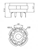
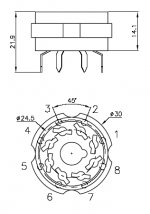
Made a quick drawing of the Octal tube socket I have.
The diameter of 24.5mm is the pitch diameter for the holes in the PCB. Tolerance for al dimensions is ±0.15. I hope this get's you started for an overall setup of the PCB.😉
Regards
Thanks for the picture, can you get some measurements to Al so he can continue with the board design?
Made a quick drawing of the Octal tube socket I have.
The diameter of 24.5mm is the pitch diameter for the holes in the PCB. Tolerance for al dimensions is ±0.15. I hope this get's you started for an overall setup of the PCB.😉
Regards
Attachments
GG preamplifier
Hi,
I have been planning on building a GG preamp (thanks for the support Mark) and this project seems to be the way forward.
One question, has anyone considered a remote control GG?
Probably most will use a potentiometer but I would like to use a RC relay ladder arrangement. Let me know if anyone else is interested and their thoughts.
Barry
GeWa-
Thank you for the pictures!
Mark/Al-
So will there be a spot to mount a tube socket on the PCB or just pads to tie the socket leads to the PCB via short jumpers? The second would allow the use of different tubes, but then loses some simplicity.....
Thank you for the pictures!
Mark/Al-
So will there be a spot to mount a tube socket on the PCB or just pads to tie the socket leads to the PCB via short jumpers? The second would allow the use of different tubes, but then loses some simplicity.....
So will there be a spot to mount a tube socket on the PCB or just pads to tie the socket leads to the PCB via short jumpers? The second would allow the use of different tubes, but then loses some simplicity.....
I realize that we can solder tube sockets to pcb's all day long, its really easy and relaxing as well. But I would prefer to see the latter so its a more universal type of board. Some may want to go the 12SN7 route and some may want to go the 12AU7 route or something different yet. To me it makes sense to only make one board that fits all purposes. The circuit topology is the same for any tube, it just involves different value parts. If we make two or three the prices will be alot higher. We need to be able to order at least 200 boards to keep costs down. I feel that soldering wires from the board to the socket is pretty trivial for all of us to do.
One thing I will make clear is that I won't stop anyone fomr designing a board with the tube sockets aboard it. One could still solder wires from the tube socket positions to different types of sockets. What ever we all agree on is fine.
Today I picked up a filament transformer, and most of the resistors and caps they I need to get the first one going as well as three octal sockets. I'm just going to build this thing on a breadboard for the R&D stage so we can get going on a PCB design. I plan on using my trusty Eico H-V Bench supply but I do need to build up some sort of negative supply as I only have one bench supply. Hopefully we will see at least some progress by the weekend on this thing.
One good thing about using 12SN7's aside from the generally lower price is that the filament current is the same as the 12AU7 so the same filament supply can be used on both versions. This can be a simple TO-3 regulator IC set to 12.6 volts. I did this in my 12AU7 GG and I run my filaments at 12.6 volts the Rosenbilt kit version runs them at 12 volts, but I think emission is a tad bit better at 12.6, he claims longer life but to me the thing sounds better at 12.6.
As to remote volume its a good idea but complicates it alot. Its almost two seperate projects at that point! I have some NOS Daven attenuators that I strip out all the old junk out of and build a new ladder type in it.
Mark
check this out
sorry i jump here just want to say...
anyone wants build pcb? check this out:
http://www.nrgrecording.de/html/pcb.html
want good preamp mic? look at :
http://www.gyraf.dk/
cheers everyone
sorry i jump here just want to say...
anyone wants build pcb? check this out:
http://www.nrgrecording.de/html/pcb.html
want good preamp mic? look at :
http://www.gyraf.dk/
cheers everyone
No one answered the low vs high voltage 6SN7 version
Anyone try the 200 volt vs 350 volt positive & negative rails on the 6SN7 tube?
Another very interesting fact is many report that auditioning various brands of 12AU7s produces little sonic differences. That is most unusual.
BTW- I am building a hard wired 6SN7 GG preamp. I may try a low voltage test, but am focused on the high voltage version.
- Status
- Not open for further replies.
- Home
- Amplifiers
- Tubes / Valves
- Grounded Grid Preamp Project And Possible Group PCB Buy