I forgot to mention that there is a +/- voltage used in the GG +/- 200 volts in the oroginal and +/= 350 in the 6SN7 version. Aything around these levels is very dangerous and can be quite lethal if proper care is not followed.
Mark
Mark
I just think calling it a grounded grid circuit is a bit misleading and contrary to accepted terminology
Absolutely right! This really should be called a differential pair ("long tail pair"), where the cathodes are always coupled to each other. The fact that the loads on each plate are different doesn't change this designation. Calling this grounded grid (which implies direct signal input to the cathode) is misleading. Audio Research's MCP-33 was a true grounded grid preamp. See:
http://www.arcdb.ws/MCP33/ARC_MCP33_schematic3.jpg
It doesn't matter what the heck you call it...
It is a Cathode follower first stage driveing a Grounded Grid second stage..... but they share the same resistor...
To be a true diff pair, both halves of the diff pair should be matched ....in this case they are hardly well matched...
Chris
It is a Cathode follower first stage driveing a Grounded Grid second stage..... but they share the same resistor...
To be a true diff pair, both halves of the diff pair should be matched ....in this case they are hardly well matched...
Chris
It doesn't matter what the heck you call it...
Well, the circuit itself could care less, but since we use nomenclature to help us communicate, we ought to be consistent with convention unless there is a compelling reason to depart from convention (none here). When we start throwing terms around without using commonly understood conventions, we risk confusion, especially among our newbie friends.
It is a Cathode follower first stage driveing a Grounded Grid second stage..... but they share the same resistor...
Sure it is, but you just described ALL such differential amps. You could also have said it's two CFs joined at the cathodes. Common usage is not to refer to it as a CF/GG or CF/CF. The term GG has long implied a stage where the cathode is driven first by the input signal, and has low input impedance, current gain of one, and the potential for high voltage gain, and is non-inverting.
One concern is the oft-heard complaint that "I don't like CFs" (earlier in this thread, too). Well, a diff amp is just two CFs joined at the hip with a common large resistor to a lower voltage. But the problems with CFs largely are cancelled in the diff amp configuration.
As I said before, the circuit doesn't care what we call it, and I'm not suggesting that there is anything wrong with this circuit approach. In fact it probably will do just fine.
Well, the circuit itself could care less, but since we use nomenclature to help us communicate, we ought to be consistent with convention unless there is a compelling reason to depart from convention (none here). When we start throwing terms around without using commonly understood conventions, we risk confusion, especially among our newbie friends.
Agreed.....
Sure it is, but you just described ALL such differential amps. You could also have said it's two CFs joined at the cathodes. Common usage is not to refer to it as a CF/GG or CF/CF.
Not at all... This is not a differential input pair by definition...
These two stages are not matched and do not benefit any DIFF features, especially common mode insensivity, not to mention input offset..also they do not have matched frequency response..
The second stage by definition is not a cathode follower....
The term GG has long implied a stage where the cathode is driven first by the input signal, and has low input impedance, current gain of one, and the potential for high voltage gain, and is non-inverting.
Agreed....
Chris
OK, one more go around on this and then I'll just chalk it up to semantics.
Many, if not most, differential amplifiers in use do not have balanced loads (especially BJTs or FETs). Balanced loading is not a prerequisite for a diff amp. Look at any op amp schematic. The real point is that at least one side's plate does respond to the DIFFERENCE between the two grids' voltages (or a close facsimile thereof). In this case, one grid's input is the incoming signal, the other grid's input is the feedback. Two inputs, one output responding to the diff - a diff amp. Just like any op amp. (Are we looking at the same circuit?)
Not so quick. Depends how you look at it. Although the second stage does have a plate load, its cathode is driving the common cathode node (as a sort of CF) creating a differential response that then effects the voltage across the plate resistor. My point was only to say that you could view circuits in all kinds of ways and then give them a name that might confuse others. That's all.
🙂
Not at all... This is not a differential input pair by definition...
Many, if not most, differential amplifiers in use do not have balanced loads (especially BJTs or FETs). Balanced loading is not a prerequisite for a diff amp. Look at any op amp schematic. The real point is that at least one side's plate does respond to the DIFFERENCE between the two grids' voltages (or a close facsimile thereof). In this case, one grid's input is the incoming signal, the other grid's input is the feedback. Two inputs, one output responding to the diff - a diff amp. Just like any op amp. (Are we looking at the same circuit?)
The second stage by definition is not a cathode follower....
Not so quick. Depends how you look at it. Although the second stage does have a plate load, its cathode is driving the common cathode node (as a sort of CF) creating a differential response that then effects the voltage across the plate resistor. My point was only to say that you could view circuits in all kinds of ways and then give them a name that might confuse others. That's all.
Agreed....
🙂
Well, Here's Bruces quote "When I finished the design and looked at the circuit, it struck me as remarkably similar to a solid state differential amplifier. It was not my intent to mimick that topology with tubes, but that is what it took to make it work so well."
At any rate as far as I'm concerned Bruce's design is a true grounded grid as much as is the ARC design. Both have only a single stage that is running in GG fashion. For me any tube stage whose grid is grounded either directly or through a divider and modulated at its cathode has to be a GG type stage.
Mark
Seems like an expensive power supply to build.
Would need twice the inductors transformers and caps. All these parts are quite spendy.
Would need twice the inductors transformers and caps. All these parts are quite spendy.
It depends on whose version you build. The GG does not rely or really require that type of supply.
Mark
Mark
I think a grounded grid amplifier, by definition, must be one whose input is at the cathode. You will find a circuit diagram and a description of such a circuit on pp.430-432 of Terman's Electronic and radio engineering (1955). It was only really used at radio frequencies where valve capacitances become of great importance. There was a different version of the circuit we're discussing in Glass Audio in 1995, where Dirk Wright used a real cathode follower to feed a grounded grid stage which he cascaded into another cathode follower. Unfortunately he decided to call it "grounded grid", which may have inspired Mr Rozenblit's termonology. If you look for the circuit in the classic literature, you will inevitably find similar ones in the sections devoted to "cathode-coupled" stages.
Well technically there is only one stage in both Rosenblits and ARC's preamps that would be considered a GG stage. V-2 in Rosenbilts and V-1 in the ARC(since V-2 and V-4 have grids connected to the NFB line) . Both stages are oddly similar, although connected to theor following staged differently. All transmitters I've known of to use a GG confoguration only used it in either the driver or final PA. So from my point of view both preamps have one stage that is GG. BTW, I certainly consider the first stage in the Rosenblit design a cathode follower input stage. The way the thing is drawn just makes it look like a differential input.
Mark
Mark
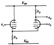
Figure from "Vacuum Tube Amplifiers", by Valley and Wallman, MIT Labs, 1948, a definitive book on basic circuits.
Second figure under the section called "Differential Amplifiers". There are dozens of vacuum tube op amp designs with similar input diff amps.
Agreed! That's how this kind of diff amp works.
It doesn't matter how it's drawn, it's still a diff amp.
It is my belief that we ought to dig up more of the old tube op amp circuits ideas from the past for use in audio. By definition, they were DC coupled circuits. Many used clever level-shifting circuits to drop DC voltages with little signal loss. However, they all needed feedback to work correctly and that will scare off some folks, but then so will this design being discussed. I personally think Rosenblitz's design looks very good (haven't heard it though); I just wouldn't have given it that name.
Second figure under the section called "Differential Amplifiers". There are dozens of vacuum tube op amp designs with similar input diff amps.
BTW, I certainly consider the first stage in the Rosenblit design a cathode follower input stage.
Agreed! That's how this kind of diff amp works.
The way the thing is drawn just makes it look like a differential input
It doesn't matter how it's drawn, it's still a diff amp.
It is my belief that we ought to dig up more of the old tube op amp circuits ideas from the past for use in audio. By definition, they were DC coupled circuits. Many used clever level-shifting circuits to drop DC voltages with little signal loss. However, they all needed feedback to work correctly and that will scare off some folks, but then so will this design being discussed. I personally think Rosenblitz's design looks very good (haven't heard it though); I just wouldn't have given it that name.
Attachments
interesting way to look at a grounded grid amp. i admit it is a bit misleading a the circuit looks to be more of a differential pair. of course there are other grounded grid designs that aren't called such. cascode would be one.
That's right. The upper tube in a cascode is really a grounded grid stage. But I think it would be misleading, according to conventional nomenclature, to market a cascode amp by the name "grounded grid".
The usual grounded grid topology probably deserves more consideration in the moving coil "headamp" location, where the low cathode input impedance is not a problem and there are certain noise benefits.
The usual grounded grid topology probably deserves more consideration in the moving coil "headamp" location, where the low cathode input impedance is not a problem and there are certain noise benefits.
One thing of note that I have heard and measured is that the original design called for 12 volts DC(regulated) on the filaments and when I accidentally blew the 12 volt regulator on day whilst making measurements I replaced it with a variable regulator and set it to 12.6 and the noise dropped considerably, like almost 2db with the Tung-Sols plugged in. Bruce claimed extra life for the toobes and thats probably true of the lower voltage but then they are not designed for 12 but instead 12.6. I still have a total cost of about 85.00 in building mine.
Mark
Mark
I replaced it with a variable regulator and set it to 12.6
Quite possibly the noise dropped because the variable regulator simply had lower noise.
Mark A. Gulbrandsen said:Thanks for the link!
Definately the same exact topology but of course all the parts values been tweeked for the 6SN7 instead of the 12AU7(or equivelent). I think I'll build it and see how it sounds as the 6SN7 certainly has its virtues
Mark
Hi Mark, I have Audio Reality and was thinking of building the GG from it after I complete my 300B which is underway. I was wondering if you were still going ahead and work on the 6SN7 version for comparison to the 12AU7? If so please post, there were some great brains working on this thread, I've watched from the beginning and got to admit it was disappointing to see it loose gas. I would have jumped in but 'too new' better sometimes to watch, learn and appreciate.
Stan
Yes, I am still planning on doing the 6SN7 version. I am on an extended road trip for work(servicing cinemas) so its going to have to wait for a week or two before I start it. But hey, I am traveling through Montana, Wyoming, and Idaho so I'm not complaining..... I won't abandon this thread either.
Mark
Mark
"or you could try this version.... Post #14
http://www.tubeaholic.com/archives/...6sn7/index.html
Just did a google and came up with a 6sn7 version of it."
____________________________________________________
The above link is now dead... anyone know this guy or what might have happened?
Mark
http://www.tubeaholic.com/archives/...6sn7/index.html
Just did a google and came up with a 6sn7 version of it."
____________________________________________________
The above link is now dead... anyone know this guy or what might have happened?
Mark
Mark A. Gulbrandsen said:"or you could try this version.... Post #14
http://www.tubeaholic.com/archives/...6sn7/index.html
Just did a google and came up with a 6sn7 version of it."
____________________________________________________
The above link is now dead... anyone know this guy or what might have happened?
Mark
I saved this link and copied it into a word document that saved all the text and schematics, should help.
Stan
Attachments
- Status
- Not open for further replies.
- Home
- Amplifiers
- Tubes / Valves
- Grounded Grid Preamp Project And Possible Group PCB Buy