Not sure I undrstood what is star grounding with I2S. If the star is the inputt ground vias, Amareno and alike are made this way so it shoud suffice. My experience differs indeed as I prefer each I2S to have its own ground return path when the pcb is tinny.
As for traffo, I always suffered of something less involved in the music at digital inputt chain and prefer isolator chips... don't ask me why.😕
Well let stop the disgress here as the board beginns with I2S inputt. But I sincerly believe the best way to improve the design is to start from a consistent prorocol for feeding the dac and here for both scope and ears, my humble opinion is to go with sd card and always involve that choice (or the one you prefer) in the discussion. And yes you should try Iancanada stuffs, not so bad and odd you didn't as a curious mind, but off topic here.
Star grounding on I2S is a way to ensure that CM noise currents (which come from the source, laptop, PC or anything which is mains powered, especially with an SMPSU) get routed back to mains without interfering with any of the audio circuitry. When coaxial inputs are used for the three I2S signals, each has its own GND return which normally will go to a groundfill - that groundfill needs to have a slot in it so those currents return to the power supply and don't travel down signal cables to the next piece of kit in line.
Hi Abrax,
Thanks for the inputt. I was aware of it but didn't know it worked for digital higher speed signal. Slot was for me the way to try to split the ground to improve the digital signal return path not to mix with the analog one when an analog and digital pins are involved on the dac chip. This slot helps to create more stable references for each of the digital and analog signal. So my understanding is you don't have return ground path near or below the I2S signals but you channel a ground path away creating a ground loop (sort of).
EMC Books
For Iancanada and John from Ecdesigns I believe you can ask them on their threads They are open minded as you are and they certainly be happy to exchange and share their experience. For John it's indeed the long tda1541a thread (thread is still active while as you wrote he is now on discrete r2r designs for his dacs). Iancanada who came from high speed signal engineering is a good source here about integrity speed of digital signals and integrity and the way to trade off with ground designs for noise.
Anyway I disgress and apologize for the readers. My point is just you should measure an listen your dac with sdcard only to have a consistency and it's certainly the best source you have in what you described just before imho. But who am I...I'm not in your shoes anx happy you share with us.
Keep the good job Abrax, I will be happy to try to populate one of your board in the near future.
Cheers
Last edited:
PCBs are in!
Brief progress update - first PCBs for the analog board and the plug-in buffers have arrived so I'll be doing build over the next couple of days and collecting all the PCB errors together for the re-spin. Plus working on the BOM.
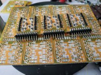
Here's a picture of the first assembled buffer plug-ins, they use a 2mm pitch connector as the gap between the rows of pins corresponds closely with the thickness of a typical PCB. When I have a built-up analog board I'll photograph that too.
Brief progress update - first PCBs for the analog board and the plug-in buffers have arrived so I'll be doing build over the next couple of days and collecting all the PCB errors together for the re-spin. Plus working on the BOM.
Here's a picture of the first assembled buffer plug-ins, they use a 2mm pitch connector as the gap between the rows of pins corresponds closely with the thickness of a typical PCB. When I have a built-up analog board I'll photograph that too.
Attachments
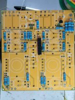
The analog board starts to take shape - I ordered 0.5W resistors, thinking they were the standard ones as in the Western world but on Taobao they turn out to be a bit over-sized. So next time I know, order 0.25W to get the standard ones! Next up - wind some inductors. The PCB gives a choice of inductors - either hand-wound (gapped P14 cores sourced locally) or commercial ones from Bourns (Mouser).
Attachments
Haha no, only a handful of them for reading bus routes. When I said 'ordered' I give my orders to my wife and she works out the best and cheapest seller to fulfill it 🙂
So far no PPS but perhaps in future I'll give them a whirl. Only NP0 on this PCB as far as SMD caps go, plus four very large leaded film caps to go on at the end.
Ask wify to get some pps for the analog side of the dac, you may like it imho. While capacitance values znd precision involve to forgett it in precise filter needs...Higher size case may stop you for inductance but the trade off worths it after a listening...most of the time. Sumo can confirm as well...
Wow designs your pcbs !!!!! bravo. Having said that, women are really really good with intricate stuff, no two ways about it Richard.

Great feeling ya Richard. Btw that filter network, though in calculation & theory it works but I do suspect it will hinder SQ more then it helps.
Which filter network do you mean? The CLC filter between the transformer output and the buffers?
Power supply Richard. Go look at EC thread last few post. Max suggested a balun filter. I tried that out & it works very well. Important is to use 1 mm enamel wire to wind. So far its the most effective filter that I've tried.
Cheers
Cheers
Sorry, you mean I have a power supply filter? Or that I need one? I did see @Maxlorenz adding a filter to his ECD DAC - I've experimented with CM chokes for quite a long time but they're only needed to deal with grounding loops. There isn't a grounding loop in my current setup. Even if there was the potential for one, the transformers defeat it.
Yes asking u to try that. I use CM before as well but never like it. Some how Max suggestion works. I made mine out of a 50mm OD powder coat ferrite ring. Started out as curiosity but results surprised me.
If you're getting improvements from a CM choke then try isolation transformers next, the result may well surprise you further.
- Home
- Source & Line
- Digital Line Level
- Grossly parallel multibit DAC adventures