Nice! I was very impressed when I saw yours on another forum a month or so ago. Really lovely work.
So you’re only going to be able to rear mount else you’ll ruin the finish and overall look. IIRC, the tweeter is sat inside a cutout that’s been made by a router. I don’t think the DM3 will fit in there so you’d have to alter the cabinet - or perhaps just shaving some of the plastic off the DM3s themselves, after all you won’t see it. I have some time tomorrow and Friday. I will open my Ks and check for you…. Maybe I’m wrong and they will fit inside it!
I’m terms of the oily residue, I don’t think that would alter the sound measurably, but it does draw your eye. Do you know what capacitors the tweeters were recapped with? If they’re electrolytics then you could start by swapping out with polys and see if that helps.
In any case, you’ll definitely get an improvement from the DM3s over those…. How confident would you be cutting into some of the crossover wires and soldering in a small inductor? You’d have to trace the wires and compare to the diagram and make sure you don’t bridge something you shouldn’t. Else you could always try doping them. My DM3s in the K2s only have a 4.7uF cap and that’s it.
Thanks Ellnic,
I was more worried about the residue when I thought it was a recent thing.. but after checking old photos it’s definitely been there for a long time. So I’m primarilly interested really in having a plan B in the future should any of the drivers fail really (I’ve been on the look out for a spare magnum k for a long time to future proof them)
I might buy the tweeters and keep them in the drawer just in case or till i feel like having a play. Are you able to let me know what I would inductor i would need to install, and where if i replaced the tweeters - I’m sure i can rout out the back / modify them to make them fit physically if i do that. I’ve attached a pic of my refurbed crossover and the Goodmans tweeters that are for sale locally. Cheers.
Attachments

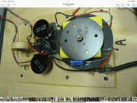
Ah! I see something. Looking at your crossover you appear to have 2 larger poly caps (the yellow ones), but that smaller blue one that is connected to the LPAD - that’s the LPAD for the tweeter. This won’t be helping, because that smaller blue one is electrolytic. Electrolytics don’t pass high frequencies very well (I don’t use them at all and whenever I get a pair of speakers I always recap with polys across the board). Polys are much larger than electrolytics (hence you have a custom bracket there holding them in place) and they can be a lot more expensive but the upside is they sound better and they don’t need replacing.
The value from the original crossover is 4uF. You don’t have to get 4uF exactly, a little bit either side won’t hurt. The lower the number, the less of the low frequencies it will let through. I know a very reliable seller on Ali who does decent caps for not a lot:
https://a.aliexpress.com/_ExjLzyF
I have measured his caps and they are always within tolerance. He says 3% but I find it to be less than that more often than not.

They are sold in singles. A pair of the 3.9s should do the job nicely. I’d probably try this first and see what they sound like. You may be surprised.
If you want to swap out the tweeters, you’ll need to visit this seller: https://a.aliexpress.com/_EzR5gPH
And get one of these:

And you would need to place it here:

So after the 4uF cap, with the other end to ground. You can do this easily. Just put one end of the inductor connected to the wire that joins the blue capacitor (hopefully soon to be red) to the LPAD and the other end connect to the negative post.
If those tweeters you’re thinking of buying are cheap enough, I’d say go for it, grab the inductors too then you have those as a backup plan.
One final thing, if you do go down the inductor route, you’ll need to place it on your rear panel in a certain way as inductors can interfere with each other. You shouldn’t have inductors close to each other if they are the same orientation so you should probably place it here or here:

But the same way (on its end) like the small one. That way the fields won’t interfere with that large one. The position by the letter A is ideal - but perhaps a bit further away - an inch more should do nicely. Depending on how much spare they give you on the legs, you can just solder a bit of extra wire to them. If the solder isn’t sticking it’s because the wire is enamel coated. Scrape the ends off with a blade and you’ll see the colour change (they probably will have done this for you though).
Let me know what you decide and how you get on! 🙂
The value from the original crossover is 4uF. You don’t have to get 4uF exactly, a little bit either side won’t hurt. The lower the number, the less of the low frequencies it will let through. I know a very reliable seller on Ali who does decent caps for not a lot:
https://a.aliexpress.com/_ExjLzyF
I have measured his caps and they are always within tolerance. He says 3% but I find it to be less than that more often than not.
They are sold in singles. A pair of the 3.9s should do the job nicely. I’d probably try this first and see what they sound like. You may be surprised.
If you want to swap out the tweeters, you’ll need to visit this seller: https://a.aliexpress.com/_EzR5gPH
And get one of these:
And you would need to place it here:
So after the 4uF cap, with the other end to ground. You can do this easily. Just put one end of the inductor connected to the wire that joins the blue capacitor (hopefully soon to be red) to the LPAD and the other end connect to the negative post.
If those tweeters you’re thinking of buying are cheap enough, I’d say go for it, grab the inductors too then you have those as a backup plan.
One final thing, if you do go down the inductor route, you’ll need to place it on your rear panel in a certain way as inductors can interfere with each other. You shouldn’t have inductors close to each other if they are the same orientation so you should probably place it here or here:
But the same way (on its end) like the small one. That way the fields won’t interfere with that large one. The position by the letter A is ideal - but perhaps a bit further away - an inch more should do nicely. Depending on how much spare they give you on the legs, you can just solder a bit of extra wire to them. If the solder isn’t sticking it’s because the wire is enamel coated. Scrape the ends off with a blade and you’ll see the colour change (they probably will have done this for you though).
Let me know what you decide and how you get on! 🙂
Last edited:
Thanks for your reply ellnic, I’ll let you know how I go. I think I’m going to take the lpads out the circuit again (i’ve done that before) so when i get the backs off again i might try the capacitor first.
Keen to follow how you go with your K2’s as well.
Keen to follow how you go with your K2’s as well.
Yes >
If I was you, I would remove the tweeter's Lpad for good, and definitely replace that blue electrolytic capacitor.
Although a little bit technical, if you decide to add an inductor (after) the tweeter's capacitor, you will need to
reverse the tweeter's positive and negative wires. This is because adding the inductor shifts the crossover frequency
phase relationship by 180 degrees. It's just how things work.
A capacitor of 3.9uF + inductor of .7mH will give you a crossover frequency of roughly 2.7Khz.
I would choose an inductor of .6mH rather than .7mH , = 3Khz.
CHEERS 🙂
Thanks for your reply ellnic, I’ll let you know how I go. I think I’m going to take the lpads out the circuit again (i’ve done that before) so when i get the backs off again i might try the capacitor first.
Keen to follow how you go with your K2’s as well.
I would definitely remove the LPADs. When I rebuilt the crossover for the scruffy Ks that I have, I made a point of doing this. I think they sound better fully open and it’s a point of failure removed. My K2s are completed, if you want more info, see here: https://hifisubjectivist.org/viewtopic.php?f=17&t=51631 this is my thread where I got some help before I started doping. Here’s another one: https://hifisubjectivist.org/viewtopic.php?f=17&t=47974&hilit=Doping+Magnum search the forum for “Doc mod”, you should be able to get a feel for the kind of modifications I’ve made to my K2s. Unfortunately it seems the resident expert on these kinds of mods has passed away, but the other guys there were very helpful.
@Mister Audio thanks for the pointers on the inductor. I quoted the 0.7mH just because that’s what’s in there out the factory, but as you say a 0.6mH will suit better.

Thanks for attaching that, a good read. 🙂
I suspect if you noticed a big improvement as you say, then your Lpads were probably not in their best condition.
I had considered purchasing replacements but they are NOT cheap. About £25 each in the UK and no real difference on Ali, which surprised me. I couldn’t believe that what essentially seems to be 2 pots could be so expensive, so I came to the conclusion that it’s one of those things that’s expensive “just because you want it” so I thought sod that.
I’ve seen some people who wanted to preserve them, but not replace them, drill a hole in the back, dump a load of contact cleaner in and give them a good twiddle for a few minutes (ooh er). But at the end of the day I like the sound with them removed and it frees up 2 holes for posts:

Excuse the added cat 🐱
I don’t like spending money if I don’t have to so I ripped these posts out of a pair of mission 750s I got given. I always thought they sounded bloody awful even after a rewire and recap so I stripped some of the parts and got rid of them.
So if they sound great without the Lpads, you may find that a degraded Lpad is exactly what was causing your noticeable decline. What’s the bet that:
No Lpads + Poly Cap + Super tweeters will restore them to their former glory? 🙂
I suspect if you noticed a big improvement as you say, then your Lpads were probably not in their best condition.
I had considered purchasing replacements but they are NOT cheap. About £25 each in the UK and no real difference on Ali, which surprised me. I couldn’t believe that what essentially seems to be 2 pots could be so expensive, so I came to the conclusion that it’s one of those things that’s expensive “just because you want it” so I thought sod that.
I’ve seen some people who wanted to preserve them, but not replace them, drill a hole in the back, dump a load of contact cleaner in and give them a good twiddle for a few minutes (ooh er). But at the end of the day I like the sound with them removed and it frees up 2 holes for posts:
Excuse the added cat 🐱
I don’t like spending money if I don’t have to so I ripped these posts out of a pair of mission 750s I got given. I always thought they sounded bloody awful even after a rewire and recap so I stripped some of the parts and got rid of them.
So if they sound great without the Lpads, you may find that a degraded Lpad is exactly what was causing your noticeable decline. What’s the bet that:
No Lpads + Poly Cap + Super tweeters will restore them to their former glory? 🙂
Last edited:
They're sounding pretty good with the l pads out and the Townsend Super Tweeters - extraordinary actually.
If you end up with a spare tweeter you don’t need once you finish with the k/k2 mods please let me know. Given the small tear and oily stuff on mine I’m on the look out for a replacement/spare. Cheers
If you end up with a spare tweeter you don’t need once you finish with the k/k2 mods please let me know. Given the small tear and oily stuff on mine I’m on the look out for a replacement/spare. Cheers
Interesting finding - taking the lpad completely out (desoldering the wires and connecting them separately ) sounds good at first and then - not quite right.. unbalanced.. brash.
However, if I instead leave all the ground wires attached to the lpad and both of the other wires incl the positive speaker feed joined to the centre terminal of the lpad they sound right. In this configuration the lpad is fully on (unless turned all the way anticlockwise when it suddenly turns the driver off). There is no volume adjustment -it’s either on or off.
It says to me that the lpad plays an important part in the circuit somehow so needs to be left in albeit the wires connected to ground and centre. At least to my ears it sounds right anyway.
With mine as stock and with the lpad mod done they sound fantastic.
Just reading some emails from when I played with these last I can see that Falcon audio in UK had suggested to me the same configuration of wiring when I did the initial build.
One day, the Lpad might fail intermittently.However, if I instead leave all the ground wires attached to the lpad and both of the other wires incl the positive speaker feed joined to the centre terminal of the lpad they sound right. In this configuration the lpad is fully on (unless turned all the way anticlockwise when it suddenly turns the driver off). There is no volume adjustment -it’s either on or off.
Last edited:
Sure np, I’ll let you know if I remove the tweeters and have the originals spare - but you may be better just grabbing those K2 dome tweeters and fitting those - once you factor in that they’ll sound better and they’re probably cheaper than me sending you mine (you’re in Aus, right?). I’ve been really busy the last few days so I’m sorry I haven’t had the time to size up the tweeter like I said. I will do this as soon as I can.
I don’t know much about how the Lpads work but however they’re connected where the driver just turns off when they’re fully closed doesn’t sound good to me. When you bypass them, It’s possible that they’re just a bit too loud for your liking so I think this is what @chrisng is getting at, remove completely but then use a resistor to taste and eliminate the [inevitable] point of failure. Lpads are kind of crap unless brand new (and the jury is still out on that one too if you value sound quality). When I removed mine I rebuilt the crossover completely:

Everyone’s ears are different but I think they sound freakin’ awesome like this. 😀
I don’t know much about how the Lpads work but however they’re connected where the driver just turns off when they’re fully closed doesn’t sound good to me. When you bypass them, It’s possible that they’re just a bit too loud for your liking so I think this is what @chrisng is getting at, remove completely but then use a resistor to taste and eliminate the [inevitable] point of failure. Lpads are kind of crap unless brand new (and the jury is still out on that one too if you value sound quality). When I removed mine I rebuilt the crossover completely:
Everyone’s ears are different but I think they sound freakin’ awesome like this. 😀
Last edited:
All good. The shop hasn’t responded about those replacement tweeters so that may not be an option for me.
I have another option from a guy who may have spare drivers I can purchase.
I appreciate the feedback and I’ve a couple of options there to try.
But yes let me know if you have any drivers spare once you’ve finished and how much you’d want for a spare Tweeter. Cheers.
I have another option from a guy who may have spare drivers I can purchase.
I appreciate the feedback and I’ve a couple of options there to try.
But yes let me know if you have any drivers spare once you’ve finished and how much you’d want for a spare Tweeter. Cheers.
Hi ellnic ..... I love the look of your completely rebuilt crossover in the above photo ........ I want to do exactly that in my K rebuild as well . Have spent weeks reinforcing the cabinets and adjusting the front baffle to take a different tweeter ( sadly one of the original tweeters was totally bung so I am putting in some ScanSpeak Discovery Tweeters D 2608 / 9130 that seem to have terrific reviews and have very similar characteristics.). Please note that I know very little about crossovers , so I'm thinking that I could build what you have if I follow the modified crossover design below ( I have just taken out the 2 L-pads in the drawing ). Could you please let me know if this is correct ..... I would much appreciate your advice.
PS : Hi shauwnmaxr .......... we chatted on Stereonet about Magnum K mods a few months ago.

PS : Hi shauwnmaxr .......... we chatted on Stereonet about Magnum K mods a few months ago.
Last edited:
@mf4ever you’ve almost got it, but you still have the connection to where the lpad would have been on the negative side of the speaker so this will short. You need to remove it like this:

Sorry for the crappy edit on my phone. 🙂
Edit: I’m sure I had a diagram I did without the pads but I can’t find it. Perhaps if we smile nicely at @chrisng he could knock up another K diagram without them and we can add it to the first post. 🙂
Edit2: if you should find yourself doing this Chris, perhaps you could add markers for positive and negative on each driver? All K drivers are in phase.
Edit3: I really wouldn’t lose sleep over the K tweeters to be honest. They’re mediocre. One thing you really need to make sure of is that the cabinet is air tight. Without this, the infinity bass driver will suffer. You have many points of possible failure in the K cabinet, so grab some gasket tape or draft excluder tape and replace all the seals. Ali does really good stuff: https://a.aliexpress.com/_EIvbzCj this is the stuff I use. Unfortunately it’s quite hard to check the Ks once reassembled because the grille is in the way of the bass driver so we can’t push it to test.
Also, if you can, disconnect that din socket and seal it from the back. This stuff works really well: https://www.builderdepot.co.uk/lumberjack-5-minute-polyurethane-wood-adhesive-liquid-750g it comes out like Vaseline, expands then sets rock solid. Run it round the inside of the cab too 🙂
Last edited:
Wow ..... thank you for the reply and the extensive advice given ...... armed with this corrected schematic I reckon I can have a go at your totally rebuilt crossover......... and with some further kindness from chrisng it will be better still.
I have sealed my cabinet within an inch of its life, so I am curious what the "pushing in the bass driver test " is ? The grills are no longer in the way as I have modified them ...... they will go back on with velcro .......... so I have easy access to the drivers.
Much appreciate your generous advice ....... Cheers.
No problem 🙂
What you’ve done sounds perfect. You’ve eliminated what I think may be the single worst point of failure on the K cabs and the reason why the K2 cab design was changed. This:

Altering the design so that these grille mount holes are filled and the grille goes on with Velcro like the K2s is what I would do, great stuff.
Take your time with the crossover and don’t forget you can always post it here for others to eye over. Providing the photos are clear and show the circuit at different angles, we should be able to see if you’re about to blow up your speakers or enjoy your new diy project ;-) the first time I did one I was a bit worried but just check, recheck and check again.
The bass push test involves pressing on the cone of the driver gently but firmly and evenly. If the cab is indeed air tight, it will be firm to the push and immediately spring back out when released. This happens because the air pressure in the cab is briefly increased, then returns to normal on release (think how an unopened drink bottle feels when you squeeze it). If you find that it goes in with a sort of “sinking into cornflour” feeling (not sure how else to describe it) then on release is coming out slowly, you have a leak. This is because the air was slowly pushed out through the pin hole wherever it is, then slowly returns back to the cabinet pulled back in by the driver when it returns to its resting position. You will find some people / forums claim the opposite! I have heard this reversal is particularly common on some American forums - however it is absolute boll**** and should be disregarded. Not immediately springing back = leak.
What you’ve done sounds perfect. You’ve eliminated what I think may be the single worst point of failure on the K cabs and the reason why the K2 cab design was changed. This:
Altering the design so that these grille mount holes are filled and the grille goes on with Velcro like the K2s is what I would do, great stuff.
Take your time with the crossover and don’t forget you can always post it here for others to eye over. Providing the photos are clear and show the circuit at different angles, we should be able to see if you’re about to blow up your speakers or enjoy your new diy project ;-) the first time I did one I was a bit worried but just check, recheck and check again.
The bass push test involves pressing on the cone of the driver gently but firmly and evenly. If the cab is indeed air tight, it will be firm to the push and immediately spring back out when released. This happens because the air pressure in the cab is briefly increased, then returns to normal on release (think how an unopened drink bottle feels when you squeeze it). If you find that it goes in with a sort of “sinking into cornflour” feeling (not sure how else to describe it) then on release is coming out slowly, you have a leak. This is because the air was slowly pushed out through the pin hole wherever it is, then slowly returns back to the cabinet pulled back in by the driver when it returns to its resting position. You will find some people / forums claim the opposite! I have heard this reversal is particularly common on some American forums - however it is absolute boll**** and should be disregarded. Not immediately springing back = leak.
Apologies, disregard that lumberjack glue I posted above. I’ve just realised that one is the liquid. It might work but I can’t vouch for it….
This: https://www.toolstation.com/5-minute-polyurethane-wood-glue-gel/p78519 is definitely the stuff I used. I got it from TS, too. It’s a bit pricey but it goes a long way and I figured is a great shed item ;-) once it sets hard, you can layer it as well, and it sands nicely. I ran it round all the joins in the cabs and fingered it in (ooh er), the post/crossover plate, the bass driver screw holes (I was getting air leaks there) and I have found it very versatile and well worth the money.
Edit: warning! It expands more than you’d think!
Edit2: Bass screw hole leaks only applicable to K2 because they’ve been adapted to secure from the front - with screws instead of the massive bolts.
Last edited:
- Home
- Loudspeakers
- Multi-Way
- Goodmans Magnum K (and K2) crossover diagram needed