🙂 How long were those caps run for before the listening tests?
Good point, they are brand new or NOS.
I will try some more times.😉
R12 (VR 220R) that doesn't need because you are using caps for feedback. The purpose of this VR that is adjust offset due GM Mimesis which have DC coupling.
Your schematic is the combination of GM Mimesis and Telos.
Your schematic is the combination of GM Mimesis and Telos.
R12 (VR 220R) that doesn't need because you are using caps for feedback. The purpose of this VR that is adjust offset due GM Mimesis which have DC coupling.
Your schematic is the combination of GM Mimesis and Telos.
Even in a non-DC coupled design you do need DC adjustment. So the VR is necessary.
In fact you also need to have DC output protection. If your design is DC coupled, then that protection is mandatory.
I usually tightly match load resistors, cascode transistors, degeneration resistors to keep low output offset. The result is very good if you perform that process. Output offset isn't higher 2mV. Please note that i used same circuit with Goldmund but LTP biased higher, about 15mA LTP.
Of course that things will more cost than use a VR.
Of course that things will more cost than use a VR.
His discoveries become apparent when an extremely high AC voltage is presented across the capacitors, i.e. they are used as filters to expose the distortions.His discoveries were quite surprising, at least for me.
The voltages across the NFB capacitors are very small when the amplifier is operating properly.
Lowest quality = highest distortion comes from a single polarised electrolytic used as a filter.
High quality = low distortion, comes from a single polarised electrolytic that has very low voltage imposed on it.
Very high quality comes from a series pair (one inverted) of polarised electrolytic with very low voltage.
Ultra low distortion comes from a series pair of bi-polar electrolytic with very low voltage.
If you don't believe how low the voltages are across the NFB capacitor, then start up an LTspice simulation and ask it to predict the AC and DC voltages for you.
You don't need high voltage electrolytics for NFB DC blocking duty.
Any voltage from 5Vdc up to 16Vdc is acceptable. Add protection diodes across the LV electros, if you want them to survive an output slew to Supply Rail.
Last edited:
reform your electrolytics before assembling your amplifier.Good point, they are brand new or NOS.
I will try some more times.😉
Andrew,
Who mentioned high voltage biplars for the NFB?
I have several LTSpice sims open now, and the voltages on both extremes of the NFB capacitor is in mV or nV,
What should be tried more, at least there where capacitances have to be large, is that bipolar series caps.
Who mentioned high voltage biplars for the NFB?
I have several LTSpice sims open now, and the voltages on both extremes of the NFB capacitor is in mV or nV,
What should be tried more, at least there where capacitances have to be large, is that bipolar series caps.
Andrew,
Who mentioned high voltage biplars for the NFB?
I have several LTSpice sims open now, and the voltages on both extremes of the NFB capacitor is in mV or nV,
What should be tried more, at least there where capacitances have to be large, is that bipolar series caps.
Eric is showing 35V electrolytics in the NFB DC blocking position.This is a latest 2017 version of GM reference schematic.
Some state that these electrolytics should be rated higher than the supply rail. Some others even claim that using >=100V rated electrolytics perform better when used as DC blockers.

Now, do you still think I offer fake parts?
Hi erikovsky,
I have apologized to you in the previous posts. Just that I need to be more careful after I've bought a few fakes. Please understand for that.
I will get back to you soon enough so that you can assist me in making a correct Goldmund M9.2.
Best regards,
Last edited:
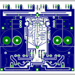
The 4700uF at 100V caps that are supplying or receiving the current to and from the loudspeakers are expected to do it by passing it all though four tiny copper track links from each solder pad. What's that going to do to the output impedance? It's not going to improve it. Might those tiny links evaporate with 8 amps to large less sensitive speakers?
The 4700uF at 100V caps that are supplying or receiving the current to and from the loudspeakers are expected to do it by passing it all though four tiny copper track links from each solder pad. What's that going to do to the output impedance? It's not going to improve it. Might those tiny links evaporate with 8 amps to large less sensitive speakers?
There are only 3 baby copper links around the pad of the 4700uF/100V capacitor, and there is a large copper link (app 0.2 inch).
That's Eagle Layout's fault when I plan them by with = 0.16". The thickness of copper is 2oZ. I think with a minimum of 0.2 inches is not a problem. But it would be better if they were 100% sealed around the pad.
Last edited:
Hi anyone,
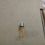
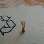
What about If I'm tried replacing the Sony 2SK43 (Rank 3 or 4) to 2N5565. I see they have Cis and Gm/Yfs best match when compared to 2N5565.
Thank all.
What about If I'm tried replacing the Sony 2SK43 (Rank 3 or 4) to 2N5565. I see they have Cis and Gm/Yfs best match when compared to 2N5565.
Thank all.
Last edited:
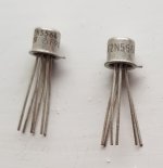
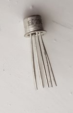
I don't have the 2N5565 but I do have the 2N5564 and 2N5566 which look like this (originals from the '80s):
Thank m0rten,
I have seen various versions of GM being posted on 6moons.com, hifishack.com, hifido.co.jp ... They could be yellow pin or silver pin, zinc sheaths are also different.
They vary depending on different fabrication times and different manufacturers !?
If hard to find. I can use the Sony 2SK43 for replace yet !?
> chientechnical
Sorry, I am not experienced enough to recommend substitutes. I have to see what other builders of the Goldmund amp suggests myself 🙂
I will try the 2N5564 in one of my projects though.
Sorry, I am not experienced enough to recommend substitutes. I have to see what other builders of the Goldmund amp suggests myself 🙂
I will try the 2N5564 in one of my projects though.
Last edited:
I'm also building Goldmund M9.2 from Naggy schematic.
But I'm can't sure the 2N5565 I having original.
Nice layout! Good job!😉
Nice layout! Good job!😉
This compliment was sent to Goldmund because I only learned from them, with only a few modifications without 24 pins module.
- Home
- Amplifiers
- Solid State
- Goldmund Wiki and build 2017