Hello ! I originated this thread, and I am still interested in members that have assembled the original version (if any) of this amplifier. Please check the first post with the original information.
I bought these boards from Nagys. In the middle there was a long story, basically because some members decided to improve this amplifier. But I want to take advantage of the boards I have and a box of components.
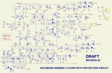
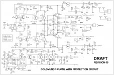
I made a new drawing of the amplifier that includes the original protection circuit, which is strange. It came to me handwritten and don't know if it matches the traces in the PCB.
Then I would like some advice to power on this amplifier. Thank to AndrewT that corrected my transcription of the original. Here is the corrected version up to date. I think it is OK now.
I am NOT interested in improved versions at this time. Just to finish these 2 boards I have as they are.
I tried to follow other posts with totally improved versions, changing almost all of the original design, but (as always) I could never finish following the results. The threads suddenly stopped and leaved many interested followers without results or conclusions . Just like that.
So if there is somebody could help me with some advice to check my circuits, power up and test these original boards, I will thank you very much.
In return, I can offer to draw new PCB's with some correction if needed, but based on the original circuit. Also my compromise of publishing a neat and complete set of documents as a contribution to this forum.
Later, and with the same spirit, proven improvements with documentation could be tried, even those that I have seen in parallel threads but with lack or confused information.
Thank you in advance.
I bought these boards from Nagys. In the middle there was a long story, basically because some members decided to improve this amplifier. But I want to take advantage of the boards I have and a box of components.
I made a new drawing of the amplifier that includes the original protection circuit, which is strange. It came to me handwritten and don't know if it matches the traces in the PCB.
Then I would like some advice to power on this amplifier. Thank to AndrewT that corrected my transcription of the original. Here is the corrected version up to date. I think it is OK now.
I am NOT interested in improved versions at this time. Just to finish these 2 boards I have as they are.
I tried to follow other posts with totally improved versions, changing almost all of the original design, but (as always) I could never finish following the results. The threads suddenly stopped and leaved many interested followers without results or conclusions . Just like that.
So if there is somebody could help me with some advice to check my circuits, power up and test these original boards, I will thank you very much.
In return, I can offer to draw new PCB's with some correction if needed, but based on the original circuit. Also my compromise of publishing a neat and complete set of documents as a contribution to this forum.
Later, and with the same spirit, proven improvements with documentation could be tried, even those that I have seen in parallel threads but with lack or confused information.
Thank you in advance.
Attachments


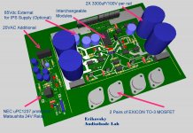
Hi Alex mm , I remember that I myself draw this schematics and corrected the 2 transcript errors. My intention was to include the protection circuit in just one single sheet. I have 2 PCB's that Nagys sold me once, and I will start populating one of them.
I will not include the protection circuit, just the components of the amplifier. What do you think about it ?
I will not include the protection circuit, just the components of the amplifier. What do you think about it ?
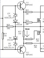
Will T14, T13, T6 turn on? How can those regulators work with the base going to earth?
And the emitter on T6 needs to be pointing to the lower voltage, not to earth. There are Hitachi and Hitachi clone circuits around which show the correct layout.
And the emitter on T6 needs to be pointing to the lower voltage, not to earth. There are Hitachi and Hitachi clone circuits around which show the correct layout.
Last edited:
Thank you very much for your advice, I will correct the circuit again so we can check. Will be back tomorrow with this.
Good afternoon.
Your products are very good
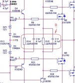
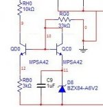
I wanted to ask for С10 С11 (see attachment) - what is the reason for choosing such a face value?
At me with such capacity between Gates the 3 harmonic grows, therefore has reduced up to 1000pF.
Your products are very good
I wanted to ask for С10 С11 (see attachment) - what is the reason for choosing such a face value?
At me with such capacity between Gates the 3 harmonic grows, therefore has reduced up to 1000pF.
Attachments
Last edited:
alex mm here is a version 5 of the corrected schematics.
Hello IanAS, there is an old discussion about the orientation of T5. It works, and Goldmund made an excellent amplifier even with this apparent "bug" and with Hitachi's examples, I have a couple of these.
As I said I am interested in working on the original version of the circuit. Here is an AC simulation of this circuit on LTSpice. There is still a trick because I took some known models of the parallel thread that do not exactly match the components used in the original Goldmund eg: LSK389A pair instead of 2N5565 , SA1381 and SC6503 in place of MPSA92 and MPSA42, 2SK1058 and 2SJ182 replacing original BUZ900 and BUZ905. Unless I am very wrong, I don't expect a dramatic difference, specially considering that mortals like me can't hear this difference and also have just a pair of TANNOY's in my living room.
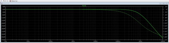
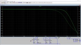
It delivered 120 W RMS into 4 Ohms load with 1.2V input. Flat from 0.1Hz to 200 KHz, almost zero phase shift to 20KHz.
I changed the original 220 Ohms trimpot to 200 Ohms and adjusted the output to 600 uV with input shorted. No Zobel network included in the simulation nor protection circuit of course.
I am sharing this results with you all and pay much attention to your opinions.
Hello IanAS, there is an old discussion about the orientation of T5. It works, and Goldmund made an excellent amplifier even with this apparent "bug" and with Hitachi's examples, I have a couple of these.
As I said I am interested in working on the original version of the circuit. Here is an AC simulation of this circuit on LTSpice. There is still a trick because I took some known models of the parallel thread that do not exactly match the components used in the original Goldmund eg: LSK389A pair instead of 2N5565 , SA1381 and SC6503 in place of MPSA92 and MPSA42, 2SK1058 and 2SJ182 replacing original BUZ900 and BUZ905. Unless I am very wrong, I don't expect a dramatic difference, specially considering that mortals like me can't hear this difference and also have just a pair of TANNOY's in my living room.
It delivered 120 W RMS into 4 Ohms load with 1.2V input. Flat from 0.1Hz to 200 KHz, almost zero phase shift to 20KHz.
I changed the original 220 Ohms trimpot to 200 Ohms and adjusted the output to 600 uV with input shorted. No Zobel network included in the simulation nor protection circuit of course.
I am sharing this results with you all and pay much attention to your opinions.
Attachments
I'm sorry obiwankenobi
But there is an error in the scheme DRAFT Revizion5 in the attachment:
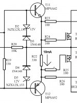
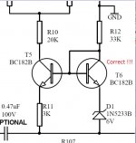
This is T6, its inclusion is incorrectly drawn.
In the original circuit it is the PNP transistor.
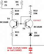
It is also desirable to shunt the zener diode with a 0.1-1 microfarad capacitor, to reduce the noise of this zener diode.
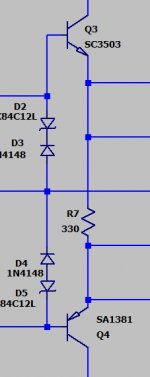
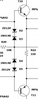
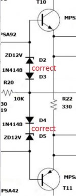
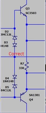
Also on the sheme DRAFT Revizion5 incorrect polarity drawn protective diodes and zener diodes D2D3D4D5
But there is an error in the scheme DRAFT Revizion5 in the attachment:
This is T6, its inclusion is incorrectly drawn.
In the original circuit it is the PNP transistor.
It is also desirable to shunt the zener diode with a 0.1-1 microfarad capacitor, to reduce the noise of this zener diode.
Also on the sheme DRAFT Revizion5 incorrect polarity drawn protective diodes and zener diodes D2D3D4D5
Last edited:
You are very welcome Henaddy !
I understand what you mean, but please take a look at these attachments again. Could you please draw a small draft for me or explain how the diodes are inverted ?
Please check the results of the working simulation. Even with a simulation working, I understand that I could have made a mistake, but I have tested inverting the diodes one minute ago, and the phase shifted a lot ! It would be nice that if you could enlighten me and be more specific at this point.
If you read my previous posts, I already explained that I am NOT willing to improve the original circuit, just test it. In the future, and once I can make the original work, I will be adding some changes here and there, such as your advice about zener diodes noise, but the original does not have any capacitor to reduce the noise across the zener. There is a parallel thread that is modifying and improving the Mimesis 3. Remember that this old Goldmund amplifier has been a winner.
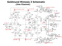
Also, please notice 2 issues: first, that one diode is a zener and the other is just a fast switching 1N4148 diode (not a zener), and in that case it could be correctly inverted. Second, I am not the author of the "original" Mimesis 3 drawing, and it has been tested in other forums as shown in the original drawing.
These new attachments show original drawing vs. my drawing vs. working simulation drawing, and also attached the output result plot of the AC working simulation with the diodes as shown. They are all the same circuit.
I am open to this interesting discussion though 🙂
I understand what you mean, but please take a look at these attachments again. Could you please draw a small draft for me or explain how the diodes are inverted ?
Please check the results of the working simulation. Even with a simulation working, I understand that I could have made a mistake, but I have tested inverting the diodes one minute ago, and the phase shifted a lot ! It would be nice that if you could enlighten me and be more specific at this point.
If you read my previous posts, I already explained that I am NOT willing to improve the original circuit, just test it. In the future, and once I can make the original work, I will be adding some changes here and there, such as your advice about zener diodes noise, but the original does not have any capacitor to reduce the noise across the zener. There is a parallel thread that is modifying and improving the Mimesis 3. Remember that this old Goldmund amplifier has been a winner.
Also, please notice 2 issues: first, that one diode is a zener and the other is just a fast switching 1N4148 diode (not a zener), and in that case it could be correctly inverted. Second, I am not the author of the "original" Mimesis 3 drawing, and it has been tested in other forums as shown in the original drawing.
These new attachments show original drawing vs. my drawing vs. working simulation drawing, and also attached the output result plot of the AC working simulation with the diodes as shown. They are all the same circuit.
I am open to this interesting discussion though 🙂
Attachments
-
 SIMULATION PLOT.jpg482.2 KB · Views: 250
 -
 WORKING SIMULATION_B.jpg42.9 KB · Views: 305
 -
 WORKING SIMULATION_A.jpg45.1 KB · Views: 901
 -
 ORIGINAL MIMESIS_B.jpg66.6 KB · Views: 920
 -
 ORIGINAL MIMESIS_A.jpg70.5 KB · Views: 937
 -
 MI SCHEMATIC_B.jpg170.6 KB · Views: 954
 -
 MI SCHEMATIC _A.jpg97.9 KB · Views: 970
Thank youYou are very welcome Henaddy !
Look at the original as correct...I understand what you mean, but please take a look at these attachments again.
Attachments
Last edited:
This is not an improvement - this is the correct drawing of the scheme.... I am NOT willing to improve the original circuit, just test it.
Maybe you on the board are correct, but the diagram is wrong
I am willing to believe.... Remember that this old Goldmund amplifier has been a winner.
These are protective diodes and zener diodes, at a normal signal level they do not work.Also, please notice 2 issues: first, that one diode is a zener and the other is just a fast switching 1N4148 diode (not a zener), and in that case it could be correctly inverted. Second, I am not the author of the "original" Mimesis 3 drawing, and it has been tested in other forums as shown in the original drawing.
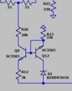
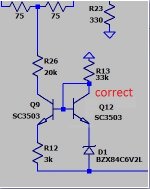
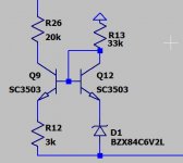
"Current Mirror Williams" must be drawn correctly.....I am open to this interesting discussion though 🙂
Attachments
Last edited:
Hennady,
Could you please draw correct position of diodes to your criteria? Or be more specific about position verbally ?
Thank you
It would be nice that if you could enlighten me and be more specific at this point.
Could you please draw correct position of diodes to your criteria? Or be more specific about position verbally ?
Thank you
obiwankenobi,Hennady,
Could you please draw correct position of diodes to your criteria? Or be more specific about position verbally ?
Thank you
I have already repainted you correctly, see the attachment in my posts above carefully.
Attachments
Last edited:
Than you Hennady, I think that you missed my text before ...
I don't know if you are aware of it, but this has been a LONG discussion about the "strange" position of the transistor in another original thread: The Very Best Amplifier I Have Ever Heard!!!!
Maybe you would like to check.
Have you seen the LTSpice simulation of this circuit that I uploaded yesterday, based upon this original circuit with the "reversed" Wilson mirror ?
It is working 🙂
I already explained that I am NOT willing to improve the original circuit, just test it. In the future, and once I can make the original work, I will be adding some changes here and there, such as your advice about zener diodes noise, but the original does not have any capacitor to reduce the noise across the zener. There is a parallel thread that is modifying and improving the Mimesis 3. Remember that this old Goldmund amplifier has been a winner.
I don't know if you are aware of it, but this has been a LONG discussion about the "strange" position of the transistor in another original thread: The Very Best Amplifier I Have Ever Heard!!!!
Maybe you would like to check.
Have you seen the LTSpice simulation of this circuit that I uploaded yesterday, based upon this original circuit with the "reversed" Wilson mirror ?
It is working 🙂
Hennady, just to honour you kind advice, I simulated the circuit with the traditional current mirror Williams circuit. Please see attachments and resulting frequency and phase shift response. Identical result, which we discussed years ago in the other thread.
Maybe you would like to explain why this "inverted" and Goldmund original circuit works as well.
Maybe you would like to explain why this "inverted" and Goldmund original circuit works as well.
Attachments
your welcomeThan you Hennady,
Sorry for the discussion I do not know, as I do not know what to discuss there.....
I don't know if you are aware of it, but this has been a LONG discussion about the "strange" position of the transistor in another original thread:
I believe...The Very Best
Amplifier I Have Ever Heard!!!!
Please check whether this transistor is properly soldered on the board....Maybe you would like to check.
current mirror Wilson in such an inclusion, as you have drawn it does not work. While the circuit will naturally be working due to the resistor in the base in 33k....Have you seen the LTSpice simulation of this circuit that I uploaded yesterday, based upon this original circuit with the "reversed" Wilson mirror ?
It is working 🙂
OK, I will check the board to see that, It will take 24 hs.
So, paying attention to this explanation, what makes the circuit work OK when simulated both ways with remarkable behaviour ?
So, paying attention to this explanation, what makes the circuit work OK when simulated both ways with remarkable behaviour ?
Easily, the circuit worked due to a resistor in the base at 33k, but the current was stable as long as the overall power of the amplifier was stable,...
Maybe you would like to explain why this "inverted" and Goldmund original circuit works as well.
The mirror of the wilson stabilizes the current of the input diffstage, due to which the circuit is not sensitive to power drawdowns at the maximum signal - you simply did not have a mode where it was possible to determine the inoperability of this device. Maybe only the Bode diagram would react like that ...
Last edited:
- Home
- Amplifiers
- Solid State
- Goldmund Wiki and build 2017